
Grease injection machine of sealed bearing make the process of grease injection fully automatic and easy to operate.
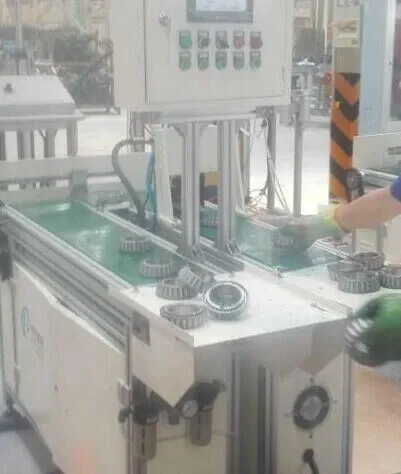
The amount of grease added to the sealed bearing is generally 1 / 5-1 / 2 of the bearing cavity. It is impossible to ensure the accurate amount of grease by manual greasing, and the labor is strong and the efficiency is low. The added grease does not enter the channel but stays on the cage. The outer diameter, end face and inner diameter of the bearing after greasing are filled with grease. Now the grease injection machine as shown in Figure 1 is adopted, so that the grease injection is automated, and the grease injection speed is up to 15 sets / min. This paper briefly introduces the working principle of the machine and its key components (the structural principle of grease injection metering cylinder and the structural design of grease injection head).
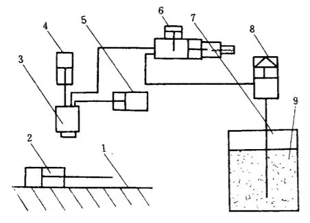
Fig. 1 Schematic diagram of grease injection machine
1. Chute 2.Pushing cylinder 3.Grease injection head 4.Grease injection head cylinder 5.Transposition cylinder 6.Grease injection metering cylinder 7.Grease storage barrel 8.Grease pump 9.Gland
1. Working principle of grease injection machine
The working process of the grease injection machine is as follows: the pushing cylinder 2 pushes the bearing to the working position (directly below the grease injection head 3) and initially positions it on the V-shaped block of the material channel baffle. The pushing cylinder 2 returns to the original position, the grease injection cylinder 4 drops, and accurately positions the bearing. At the same time, the grease injection transposition cylinder 5 pushes the grease injection head 3 to rotate, so as to automatically align and make the grease injection nozzle coincide with the bearing cage. Otherwise, the grease injection head cylinder 4 rises and falls again until it coincides. The metering cylinder 6 acts to complete one grease injection, the grease injection head cylinder 4 rises, the grease injection head transposition cylinder 5 returns, and the pushing cylinder 2 pushes the material to start the next working cycle.
The lubricating grease in the grease storage barrel 7 is fed into the metering cylinder 6 through the grease pump 8, and is accurately measured (adjustable) into the grease injection head 3 through the metering cylinder to realize accurate grease injection.
The grease pump 8 of the machine is applicable to the grease storage barrel with capacity of 180 L and 16L, i.e. standard large oil barrel and small oil barrel. It can also directly use the purchased grease barrel as the grease storage barrel. After one barrel of grease is used up, just draw out the grease pump and put it into another barrel filled with grease. There is no need to add grease to the grease storage barrel, which completely avoids mixing air during grease adding and failure of the metering cylinder, so as to ensure the cleanness of grease and the accuracy of grease injection.
2. Structural principle of grease injection metering cylinder
The grease metering cylinder is shown in Figure 2. It is the key to realize quantitative grease injection. In the figure, hole A is connected to the grease pump and hole B is connected to the grease injection head. Its working principle is as follows:
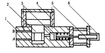
Fig. 2 Schematic diagram of metering cylinder
1. Metering cylinder block 2. Cylinder piston 3. Metering cylinder
4. Cylinder block 5. Adjusting screw 6. Adjusting hand wheel
When the piston 2 of the pilot cylinder is in the position as shown in Figure 2, the pressurized lubricating grease enters the left chamber of the grease injection and metering cylinder 3 through hole a through the grease pump to overcome the spring resistance. Because the piston rod is under the limit of the right adjusting screw 5, the volume (grease storage) of the left chamber of the grease injection and metering cylinder is certain. During grease injection, the pilot cylinder acts and the piston 2 rises, so that the left chamber of the grease injection metering cylinder 3 is connected with the grease outlet hole B. the left chamber of the grease injection cylinder 3 is pressurized. Under the action of its own pressure and the elastic force of the spring in the right chamber, the lubricating grease is quickly sprayed into the hole B and injected into the bearing through the grease injection head to complete a grease injection action. Under the control of pilot cylinder, repeated metering and grease injection can be carried out.
For different types of bearings and special requirements of users, the position of the adjusting screw can be changed by adjusting the hand wheel 6, that is, the volume (grease storage) of the left cavity of the grease injection metering cylinder can be changed, so as to meet the requirements of different grease injection.
3. Structure design of grease injection head
The grease injection head is the key to realize the accurate and uniform injection of grease onto the bearing channel. The structure of grease injection head is shown in Figure 3. The shape of the bottom of the grease nozzle is consistent with the half cage of the bearing, which is convenient for the bottom of the grease nozzle to extend between the inner and outer rings of the bearing. Make the grease spray port close to the groove of the bearing outer ring.
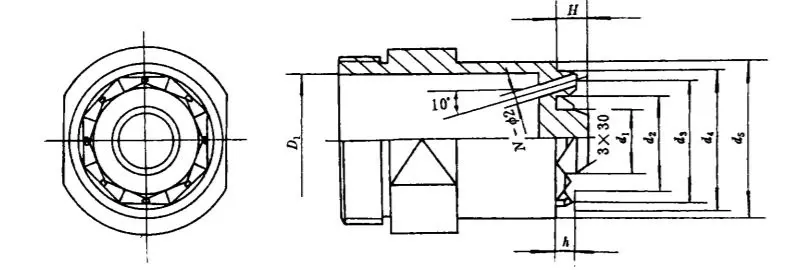
Fig. 3 Grease injection head
(1) The positioning dimension D1 is taken to ensure the accurate positioning of the bearing and avoid too tight fit with the inner diameter of the bearing to drive the bearing upward
D1 =d - (0.1 ~ 0.2)
D - Inner diameter of bearing
(2) In order to avoid interference with the outer diameter of the inner ring, the inner diameter field d2 of the grease injection nozzle is taken as
d2= D2 + (0.2~0.4)
D2 - Outer diameter of bearing inner race
(3) In order to avoid interference with the inner diameter of the outer ring, take the outer diameter d4 of the grease injection nozzle
d4= D3 - (0.3~0.4)
D3 - Inner diameter of bearing outer ring
(4) Center diameter of grease injection hole d3
d3 = (d2 + d4) / 2 + 2htg100
H - Height of grease injection nozzle
(5) Outer diameter of grease injection head d5
D5 = D
D - Outer diameter of bearing
(6) Inner diameter of grease injection head D1
D1 = D4
(7) Positioning height dimension h to ensure accurate positioning,
H = H '/ 2 + 3
H '- Bearing width
(8) Height of grease injection nozzle h to avoid collision between grease injection nozzle and cage, take
h= H '2/-S-H1-0.5
S - Thickness of cage,
H '1- Height of rivet forming head
(9) Number of grease injection nozzle holes N
N = Z
Z - Number of rolling elements
(10) Grease injection head Material plastic King
4. Features of grease injection machine
(1) The process of grease injection is fully automatic and easy to operate. The tooling has only grease injection head, so it is very convenient to change the model.
(2) The lubricating oil circuit of the whole machine is in a closed state, so there is no need to add grease to the grease storage barrel, which avoids the mixing of air in the process of greasing, affects the accuracy of measurement, and ensures the cleanliness of grease.
(3) After grease injection, the inner diameter, outer diameter and end face of the bearing are free of grease, clean, and the grease injection amount is very stable (the error is within ± 5%), and the qualified rate is 100%.
Special attention should be paid to the selection. Ensure reasonable service clearance to facilitate the normal operation of needle roller bearing and prolong its service life. Generally, the recommended clearance is 0.01 ~ 0.02 mm, and the maximum total clearance shall not be greater than (0.1-0.3) d. d is the diameter of the needle roller. The shaft fit is h5, and the roundness of the shaft surface is 0.8um.
5. Conclusion
The reasonable selection and use of engine rolling bearing can significantly improve the working reliability of engine. In order to ensure the reliability of design, it is still necessary to analyze and study the technical parameters of rolling bearing.
More about WBM Tools:
WBM Company was founded in 1988, which was located in Lilou industrial zone, Luolong district, Luoyang, PRC. WBM is a professional provider of bearing tools, including Modler End Face Grinder Tools, Rolling Dies, Cut Off Die, Quill, Cut Off Knife,cutter, Main Die, Main Die Push Out Pin, and so on. For bearing tools, WBM is definitely the most professional and best quality in China.
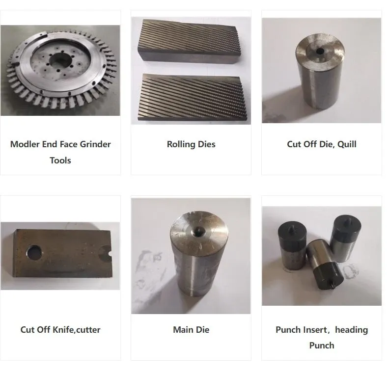
WBM now have the ability to supply full set tooling for Modler taper roller grinding line. Their tools are well fitted in customer modler centerless grinder and modler end face grinder. And help customer produce high precision rollers with low cost.
WBM has obtained the certificates of ISO9001:2000 and ISO/IATF16949, The outstanding reputation of WBM is built on our core management principles: technical innovation, high output quality and efficiency, hard-working, meeting and beyond clients’ expectation. WBM spares no effort in creating maximum value for customers.