
The working principle, main structure and service condition of MCLJ - 01 friction torque measuring instrument are introduced.
Abstract: it is very important to control the friction torque and stabilize the bearing performance to monitor the friction torque, especially the field rapid detection under mass production. MCLJ - 01 friction torque measuring instrument is developed. Its working principle, main structure and application status are introduced.
Key words: tapered roller bearing; Friction moment; Measuring instrument
Friction characteristic of bearing is an important performance index of bearing. In many applications, friction is an important cause of bearing damage. Large friction not only consumes energy, but also produces large wear, which makes the bearing lose accuracy; It will also produce too high temperature rise, burn the working surface and failure the lubricant, which will affect the fatigue life of the bearing. Therefore, people pay more and more attention to the friction torque. It is particularly important to monitor and control the friction torque, especially under the condition of mass production. At present, the existing friction torque measuring instrument can not meet the actual needs. Therefore, our company has developed MCLJ - 01 friction torque measuring instrument for tapered roller bearings, which provides a strong guarantee for our company to expand the market and a reliable basis for studying the process parameters affecting the friction torque.
1 Measurement principle
The resistance moment to bearing rotation formed by various friction factors is called the friction moment of rolling bearing. Therefore, the key of measurement is to capture the rotating resistance moment of bearing. MCLJ - 01 measuring instrument is shown in Figure 1. Its measuring principle is: the reducer motor drives the main shaft to rotate at low speed through belt drive, the inner component of the tested bearing is installed at the upper end of the main shaft, and the outer ring is installed in the bearing cover. The foot valve controls the cylinder loading, and the load acts on the outer ring of the tested bearing through the upper cover, thrust bearing and bearing cover, so that the outer ring can fully contact with the low-speed rotating inner component to generate friction, so that the outer ring has a movement trend. There is a transitional fit between the outer ring and the bearing cover, so the outer ring drives the bearing cover to make it also have a movement trend. A dowel bar is extended on the bearing cover to press the movement trend towards the force transfer block, which is transmitted to the sensor through the lever type force transfer block. Finally, the sensor transmits the signal to the display, that is, the friction moment of the measured bearing is obtained.
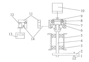
1 - reduction motor; 2 - synchronous belt; 3 - main shaft bearing; 4 - spindle; 5 - bearing pedestal; 6 - tested bearing; 7 - bearing cover; 8 - thrust bearing; 9 - upper cover; 10 - cylinder; 11 - force transfer block; 12 - sensor; 13 - display instrument; 14 - dowel bar
Figure 1 working principle diagram of friction torque measuring instrument
2 Composition
The measuring instrument is mainly composed of five parts: friction torque signal acquisition and transmission part, loading part, transmission part, measurement part and bearing installation part.
2.1 Friction torque signal acquisition and transmission part
The friction torque signal acquisition and transmission part includes bearing cover, dowel bar, dowel block, sensor and other components. It has the characteristics of simple and stable force transmission, and can complete the force transmission instantaneously, so that the measuring instrument has the advantage of rapid measurement. The sensor adopts bridge strain gauge sensor with high sensitivity and accurate measurement.
2.2 loading part
The loading part is composed of compressed air treatment (water removal), pressure regulating system, foot valve, cylinder and pipeline. The two position five way foot control valve is used to control the cylinder loading, and the load is adjusted by adjusting the air pressure. The loading range is 200 ~ 1200 kg.
2.3 transmission part
The transmission part includes reducer and motor, synchronous toothed belt and pulley, bearing, main shaft, bearing seat and other components. The motor with reducer drives the main shaft to rotate at a low speed through the synchronous toothed belt. The speed of the reduction motor is 20 ~ 150 r/min. According to the measurement requirements, the speed can be stepless regulated through the governor. The belt pulley transmission ratio is I ≈ 1. The main shaft is supported by two sets of P5 bearings. The radial runout of the connecting part of the spindle and the main shaft and the bearing support is designed as 3 μ m. Ensure the stability of the spindle drive.
2.4 measurement part
Gm8803 weighing instrument is used for measurement. This instrument has an original weighing system detection function. It can detect the working state of the sensor and force transmission mechanism before calibration, simplify the calibration process, and cooperate with the linear correction function to ensure the accuracy of calibration. The calibration method is to set the calibration value to 0 when the sensor is not under force, that is, the weighing instrument is cleared. When adding 500 g weight to the sensor, the calibration measurement value is (500 ± 5) g; When 1500 g weight is added to the sensor, if the display shows (1500 ± 5) g, it is qualified. If there is any error, linear correction shall be carried out. The instrument can also change the decimal places as required to meet the requirements of different measurement sensitivities.
2.5 measurement of bearing installation
Metric 1:5 taper fit is adopted between the external part (spindle) of the main shaft and the main shaft to facilitate the replacement of tooling when measuring different types of bearings. The clearance between the spindle and the measured bearing is matched, which can quickly load and unload the bearing and realize the rapid measurement of mass production.
3 measurement range
The measuring range of the instrument is: inner diameter Φ 25-60mm, outer diameter Φ 40-90mm, width 10-50mm, measurement accuracy: repetition accuracy ≤ 0 02 kg, measured value stability ≤ 0 05 kg.
4 Error analysis
There are two main errors in this instrument: (1) the measured value is unstable due to the runout of the spindle, and the measured value will fluctuate within a certain range. The main way to reduce this error is to improve the manufacturing accuracy of the workpiece shaft. (2) Error caused by additional torque. The additional torque generated by the whole system can be eliminated by clearing the display when it is not measured. If the additional torque generated by the thrust bearing cannot be eliminated, the friction torque of the bearing will be brought into the measured value. However, in a short time, the error value can be regarded as a fixed value and a system error, which will not affect the measurement results. The way to eliminate this error is to use air bearings, but the price of air bearings is relatively expensive, so thrust bearings are actually used.
5 Conclusion
Compared with manual measurement, this measuring instrument is labor-saving, efficient, fast and low-cost. It is suitable for mass measurement on the production site. However, because of its measurement error, it is not suitable for the accurate measurement of bearing friction torque, and is suitable for the quality control of production site.
Since the instrument was put into use, it has played an important role in the quality monitoring of the production site and provided a reliable basis for the process improvement. At present, the instrument has been in stable operation. It has been verified by production that it can meet the actual needs and meet the standards required by customers, and has made contributions to our company's market development.
More about WBM Tapered Roller:
WBM produces high-precision tapered rollers: Capacity: 10 million pcs per month ;Residual capacity: 4 million pcs per month; 5 roller production lines; 7 cold heading machines (3 Nationals, 4 Domestic); Heat treatment capacity: 9 tons per day.
Welcome to contact WBM for more information!