Classification of Cold Extrusion
- Forward Extrusion: During extrusion, the direction of metal flow is the same as the direction of punch movement.
- Backward Extrusion: During extrusion, the direction of metal flow is opposite to the direction of punch movement.
- Combined Extrusion: During extrusion, metal flows simultaneously in the direction of punch movement and in the opposite direction.
- Radial Extrusion: During extrusion, the direction of metal flow is perpendicular to the direction of punch movement.
- Upsetting-Extrusion Method: A processing method combining axial extrusion and radial extrusion.
Characteristics of Cold Extrusion
1. The deformation zone of the blank has good plasticity and high deformation resistance.
2. Extruded parts have good quality and high precision. At present, the dimensional tolerance of cold extruded parts can reach IT7, and the surface roughness Ra can reach 0.2–1.6 μm. Cold extrusion causes work hardening of the metal, makes the internal structure dense, and distributes fibers along the part contour, so cold extruded parts have higher strength, hardness, and stiffness; their wear resistance, corrosion resistance, and fatigue resistance are all relatively good. Therefore, cold extruded parts made of ordinary steel can replace precious steel.
3. High labor productivity.
4. Saves raw materials, with utilization rate reaching 70%–95%.
Main Problems to Be Solved in the Current Application of Cold Heading and Extrusion Technology
Because the unit extrusion pressure required for metal deformation in cold heading and extrusion is very high and the action time is relatively long, the current application of cold heading and extrusion technology must resolve the contradiction between the powerful deformation resistance and the load-bearing capacity of the die. To this end, the following must be achieved:
① Design reasonable cold heading and extrusion parts with good processability.
② Properly select the raw materials for cold heading and extrusion parts, correctly determine the blank shape, dimensions, and heat treatment specifications, and pay special attention to the surface treatment and lubrication of the raw materials.
③ Formulate a reasonable cold heading and extrusion process plan, reasonably select the cold heading and extrusion method, and properly control the degree of cold heading and extrusion deformation.
④ Adopt effective measures to solve the problems of die strength, stiffness, and service life, such as designing a reasonable overall die structure and correctly determining the structure, geometric parameters, and processing requirements of the die working parts.
⑤ Select suitable cold heading equipment.
I. Some Basic Concepts of Cold Heading Deformation Process
Basic Concepts of Metal Deformation
a. Structure of Metals
The structure of all metals is composed of many small crystals, which are called “grains.” The crystal structures of commonly used cold heading materials are: body-centered cubic lattice, face-centered cubic lattice, and close-packed hexagonal lattice.
b. Basic Concepts of Metal Deformation
The change in size and shape of a metal material caused by external forces is called “deformation.” Metal deformation consists of elastic deformation and plastic deformation.
The so-called plasticity refers to the ability to undergo permanent deformation under external forces without damaging its overall performance. Many parts require the material to have good plasticity during the forming process. During cold heading, some parts of the workpiece undergo very large deformation; if the plasticity of the material is poor, cracking will occur.
In engineering, the plasticity of metal materials is expressed by two indicators: elongation δ and reduction of area Ψ, which are used to measure the plasticity of the material. The values of δ and Ψ can be expressed by the following formulas
δ = (L1 - L0) / L0 * 100%
Where (L0) — original gauge length of the tensile specimen;
(L1) — gauge length of the tensile specimen after fracture.
Ψ = (A0 - A1)/ A0 * 100%
Where (A0) — original cross-sectional area of the tensile specimen;
(A1) — cross-sectional area at the fracture location of the tensile specimen.
Therefore, the larger the values of elongation and reduction of area, the better the plasticity. A material with good plasticity is favorable for forming processes such as forging, cold punching, cold heading, and cold drawing.
In principle, these two plasticity indicators can only represent the plastic deformation capacity of the material under uniaxial tensile conditions.
The upsetting test is often used in cold heading processing. In this test, the test material is made into a cylindrical specimen, with the height (H0) generally 1.5 times the diameter (D0). It is then upset on a press or drop hammer until the first crack visible to the naked eye appears on the specimen surface. At this point, the compression ratio (epsilon) is the plasticity indicator.
Where (H0) — original height of the cylindrical specimen;
(H1) — height of the specimen when the first crack visible to the naked eye appears on the side surface after compression.
The appearance of cracks in the specimen is the result of additional tensile stress acting on the side surface. Factors such as friction between the tool and specimen contact surface, heat dissipation conditions, and specimen geometric dimensions all affect the magnitude of the additional tensile stress. Therefore, when using the upsetting method to determine plasticity indicators, in order to make the results comparable, corresponding specifications must be established to explain the test conditions. In cold forging production, test specifications similar to the workpiece deformation conditions are often used to determine the suitability of the material for the cold forging process.
c. Basic Laws of Plastic Deformation
The basic laws of plastic deformation widely used in cold forging processing are: the law of constant volume and the law of least resistance.
2026 October 2nd Week WBM Product Recommendation
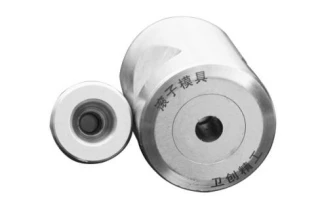
WBM produces taper roller dies with high efficiency and automation. Rollers are formed on a single automatic cold heading press and are fed, cut, and punched into the die for five steps.
We can produce different types and sizes taper roller dies with quality assurance,include:Combination Punch,Outside Sleeve,Blade,Combination Punch,Feed Cylinder,Combination Dies,Double Layer Sleeve,Insert.