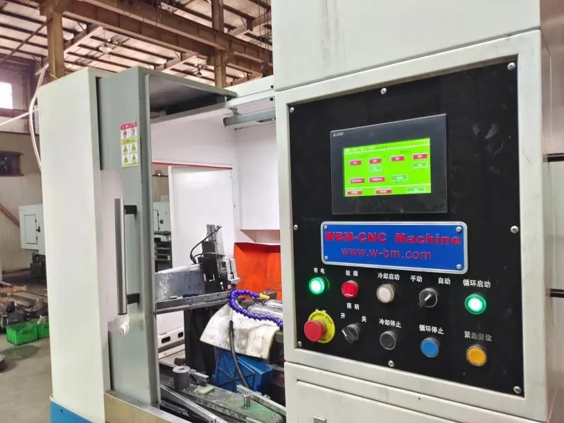
Abstract: Finished product conical roller whose half angle is greater than 3°is called large taper roller cold heading tools . Using horizontal cold header to process this kind of roller, it is difficult to keep the roller in the mould, the roller always falls from the mould. We thoroughly probe into the reason of this phenomenon, put forward the method to solve this problem, and give the calculated formula.
Key words: large taper roller cold heading tools; working sleeve; bottom mould
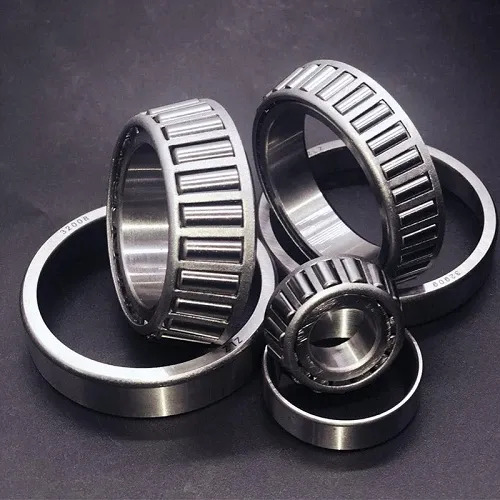
1 Introduction
There are usually two feeding methods for rollers, one is turning and forming with a lathe, the other is cold stamping and forming with an automatic cold heading machine. Generally, cold heading is preferred, because it is fully automatic, and can process more than 70 rollers in a minute. The production efficiency is quite high, and the labor intensity of workers is very low. The processing form of the automatic cold heading machine is to cut the strip into material sections at station 1 #, send it to the die cavity at station 2 #, hit the material section with a punch, and then shape it. The size of the die cavity is designed according to the size of the corresponding roller. When the cone angle of the roller is large, the angle of the die cavity is also large (so as to reduce the grinding amount of the subsequent process grinding). Since the material section is horizontal when it is placed in the die, when the angle of the die cavity is large, the material section cannot be included, resulting in material loss. In the conventional design, the concave mold cavity adopts "one" angle. For the roller with large cone angle, if the conventional design is adopted, the material will not be contained and the material will fall out. Therefore, it is assumed that the mold cavity is designed into "two" angles, the upper angle of the mold cavity is close to the angle of the finished roller, and the bottom of the mold cavity adopts a small angle, resulting in the increase of the small head diameter allowance. The specific amount of small head allowance is appropriate. It must be assumed that the diameter allowance at the parting must be calculated on a trial basis, When the allowance at the parting is close to the conventional diameter allowance (the grinding amount is the minimum at this time), the allowance is calculated by assuming that the allowance is small.
2 Mold design drawing
The punching die adopts a combined structure. The assembly drawing is shown in Figure 1, the working sleeve is shown in Figure 2, and the bottom die is shown in Figure 3.
The symbols are described as follows:
rp1 - axial chamfering coordinate of die bottom,
rp2 - radial chamfer coordinate of die bottom,
Dp - diameter of raw material,
β — Cavity draft angle,
LA - Height of working jacket,
D1 - diameter of finished roller small end,
h - maximum height of the material section from the bottom,
H1 - minimum height of the material section from the bottom,
H - parting position,
Dy - die cavity diameter at parting,
Dc - diameter of finished roller at parting,
Dyc - allowance at parting,
Dd - allowance for conventional process diameter,
δ — Finished roller half angle,
Dm - die cavity opening diameter,
L - Height of bottom formwork,
DA - maximum diameter of working sleeve,
Dm1 - lower diameter of taper hole.
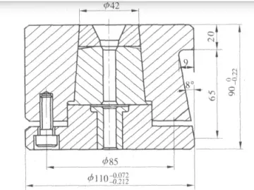
Fig. 1 Combination Diagram of Stamping Die
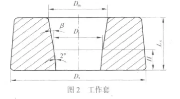
Fig. 2 Working sleeve
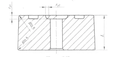
Figure 3 Bottom Formwork
3 Design formula
(1) Calculate punch position, axial chamfer coordinate rp1 constant of die bottom, radial chamfer coordinate rp2 constant of die bottom, working sleeve height LA constant, raw material diameter Dp constant and die cavity pulling angle according to conventional allowance and design method β Constant size.
(2) The lower die pulling angle of the concave mold cavity is taken as 2 °.
(3) DP=Dp+0.1mm.
(4) Estimate the diameter allowance dd1, calculate the corresponding results according to the conventional design standards, and calculate h=[(Dp - dm1)/2] × Tg2 °, determine H=h+1.
(5) Calculate h1=([Dp - dm1+material diameter deviation - cavity size deviation)/2] × Tg2 °, h1 must be greater than rp1.
(6) Calculate the allowance at the parting: ① Dy=dm1+2 × tg2° × (H- rp1) , ② Dc= D1+2 × (H- dd/2) × tg δ, ③ Dyc=Dy - Dc. When the allowance at the parting is close to the process allowance dd, the test data dd1 and its calculation results are adopted.
(7) The size of the punch part is completely based on the conventional calculation results.
(8 ) β= β Normally+10 '.
(8) LA=LA normal+rp1 normal - rp1.
( 10) Dm=Dy+2 × [ LA- (H- rp1)] × tg δ.
( 11) L=30- LA.
( 12) DA=28.2+2 × tg3° × LA.
4 Conclusion
Without this design method, tapered roller with large cone angle cannot be machined by horizontal cold heading machine. The above design method has been applied to production for several years, and the effect is very ideal. It not only reduces the labor intensity of workers, but also improves the production efficiency, saving considerable funds.
More about WBM New Taper Roller:
Here is a new taper roller product from our company. It is assured with high performance. If you have an interest in it, please let us know.
Henan Weichuang Bearing Technology Co,.td successfully finished the development of taper roller with hole in the center.Heat treatment was done by case harden. This kind of roller widely used in wind turbines bearing or special industries bearing. New energy bearing brings a new increase point in bearing market.WBM purchases two plug in type centerless grinder and one plug in type honing machine. Expand the taper rollers production capacity, now can supply roller diameter from 5 to 80mm.
1. Following are the honing machine to produce taper roller.