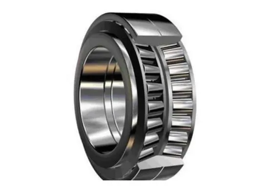
Abstract
The present invention discloses a spherical roller outer diameter ultra precision process, with the specific steps as follows: firstly, according to the size of the workpiece, after debugging, different specifications of machine tool accessories are selected; Step 2, turn on the main power supply and cooling pump of the machine tool, and select the working state; Step three, adjust the machine tool and set its parameters; Step 4, loading, use the unloading cylinder of the loading and unloading mechanism to complete the loading; Step five, the workpiece transmission mechanism drives the rollers to rotate, the swinging mechanism swings, and the ultra precision mechanism jumps into the machining position; Step 6, the ultra precision mechanism is coarse and precise; Step 7, stop the ultra precision mechanism, swing mechanism, and workpiece transmission mechanism; Step 8, material cutting, use the loading and unloading mechanism for material cutting. The present invention has a long service life; The roughness value is relatively small, after ultra precision, Ra is 0.05 μ m, roundness increases by 30%,<1 μ m, waviness decreases by 30%,<1 μ m; The spherical roller after ultra precision is installed on the elevator bearing, and the noise is reduced by 30% compared to before ultra precision, meeting the user's requirements.
Description
Superprecision technology for outer diameter of spherical rollers
Technical field
The present invention relates to the field of part processing technology, particularly to the field of spherical roller processing technology.
Background technology
There are four types of rolling elements used in rolling bearings, namely ball, cylindrical roller, tapered roller, and spherical roller. In order to achieve good rotational accuracy, low noise, long service life, and good stability, the rolling elements need to be ultra precision machined to improve their roundness, surface roughness, and waviness, thereby reducing the operating noise of the bearing and extending its service life. Currently, China has basically solved the problem of ultra precision machining of spherical, cylindrical, and tapered rollers, but has not yet solved the problem of ultra precision technology for the outer diameter of spherical rollers. At present, domestic spherical rollers can only be processed by polishing to reduce the roughness value of the roller surface, and the roughness value is also relatively large, generally around Ra 0.2 μ m. Moreover, this process causes damage to the roller surface, produces pitting, and increases the thermal stress on the roller surface. The rollers are prone to corrosion, which reduces the service life of bearings. Therefore, the development of spherical roller ultra precision machining technology, tooling, and equipment is a problem that the bearing industry must solve.
For example, the announcement date is September 22, 2010, the announcement number is 101502936, and the patent name is "Manufacturing Equipment and Processing Technology for Spherical Roller Bearings". It is disclosed that the manufacturing equipment consists of a diamond roller automatic trimming compensation system, an automatic feed grinding system, an automatic loading and unloading system, and a CNC system. The diamond roller automatic trimming compensation system is composed of a diamond roller, a grinding wheel, and a roller guide rail. The automatic feed grinding system can complete all the rough grinding, precision grinding, and final grinding work on the spherical rolling surface and two arc chamfers in one go; The specific processing technology is: 1. Blanking; 2. Precision turning of both ends; 3. Quenching; 4. Fine grind the two end faces; 5. Centerless grinding of outer diameter; 6. One time grinding of rolling surfaces and chamfering of two circular arcs; 7. Demagnetization cleaning; 8. Translucent vibration; 9. Group selection; 10. Oil coated packaging for storage. Its shortcomings lie in the high surface roughness of the processed workpiece and low production efficiency. This process is different from the roller outer diameter ultra precision process. It is the grinding process before ultra precision, and the subsequent process is the roller processing process that meets the final technical requirements.
Summary of the invention
The present invention overcomes the shortcomings of existing technology and provides a high-precision process for the outer diameter of spherical rollers with small roughness values and long service life.
In order to solve the above-mentioned technical problems, the present invention provides the following technical solutions:
The specific steps are as follows: firstly, according to the size of the workpiece, after debugging, select different specifications of machine tool tooling parts; Step 2, turn on the main power supply and cooling pump of the machine tool, and select the working state; Step three, adjust the machine tool and set its parameters; Step 4, loading, use the unloading cylinder of the loading and unloading mechanism to complete the loading; Step five, the workpiece transmission mechanism drives the rollers to rotate, the swinging mechanism swings, and the ultra precision mechanism jumps into the machining position; Step 6, the ultra precision mechanism is coarse and precise; Step 7, stop the ultra precision mechanism, swing mechanism, and workpiece transmission mechanism; Step 8, material cutting, use the loading and unloading mechanism for material cutting.
Furthermore, steps four to eight constitute an automatic loop.
Furthermore, in the fourth step, the loading and unloading cylinders drive the guide shaft to move left, and the workpiece is sent to the workpiece transmission mechanism.
Furthermore, the workpiece transmission mechanism described in step five comprises a transmission motor, a belt pulley, a belt, and a guide roller. The transmission motor drives the guide roller to rotate through a multi-stage belt, driving the workpiece falling on the guide roller to move. Each guide roller is equipped with one or two processing stations.
Furthermore, the swing mechanism described in step five comprises a swing spindle, a swing motor, a reducer, a pulley, a belt, a crank mechanism, a connecting rod, and a central connecting rod. The swing motor is connected to the crank mechanism through a reducer, and the crank mechanism is sequentially connected to a connecting rod and a central connecting rod, and the central connecting rod is connected to the swing spindle.
Furthermore, the crank mechanism is equipped with an eccentric slider.
Furthermore, the ultra precision mechanism described in the fifth step includes an ultra precision head, an oil stone wear compensation cylinder, and a pressure rod. Under the action of the oil stone jumping into the cylinder, the central pull rod of the swinging spindle pushes the screw to quickly jump the ultra precision head to the workpiece. The ultra precision head and its oil stone swing with the swinging spindle, and the jumping amount is adjusted by the adjusting screw.
Furthermore, in the sixth step, both coarse and fine ultrasound are completed by the same ultra precision mechanism.
Furthermore, as described in the eighth step, the cutting cylinder moves left and then right, and the workpiece is pushed to the right to enter the cutting channel for cutting. The first roller processing is completed.
Compared with existing technology, the present invention has the following beneficial effects:
1. Spherical rollers are not easily corroded, have a long service life, low bearing noise, and high accuracy;
2. The roughness value is relatively small, with Ra of 0.05 μ m after ultra precision, roundness increased by 30%,<1 μ m, waviness decreased by 30%,<1 μ m;
3. The spherical roller after ultra precision is installed on the elevator bearing, and the noise is reduced by 30% compared to before ultra precision, meeting the user's requirements.
Specific implementation methods
The preferred embodiments of the present invention are explained below in conjunction with the accompanying drawings. It should be understood that the preferred embodiments described here are only intended to illustrate and explain the present invention, and are not intended to limit the present invention.
As shown in Figures 1, 2, and 3, the precise process and tooling for the outer diameter of spherical rollers are as follows:
Firstly, based on the different diameters, lengths, and arc sizes of the rollers, after debugging, different specifications of machine tool fixtures are selected for ultra precision machining of the workpiece to achieve the accuracy requirements of the rollers. The specific fixtures are the guide roller of the workpiece transmission mechanism 9 and the ultra precision head of the ultra precision mechanism 20, but their working principles are the same.
The second step is to turn on the main power supply and cooling system of the machine tool, select the "automatic" or "semi-automatic" working state of the machine tool, and connect the cooling system to the ultra precision mechanism through a pipeline system through a oil pump to achieve cooling and cleaning during ultra precision machining.
The third step is to adjust the curvature radius of the machine tool parameters, and set the required speed and frequency of the workpiece transmission mechanism for coarse and fine machining, as well as the oscillation frequency and delay time of the ultra precision mechanism.
Step 4, loading is completed through the unloading cylinder of the loading and unloading mechanism 6.
As shown in Figures 4 and 5, the loading and unloading mechanism 6 includes a unloading cylinder 1, a guide shaft 2, a unloading channel 3, a blocking block 5, a roller 4, and an loading channel 7. The unloading cylinder 1 is fixedly connected to the guide shaft 2, and the unloading cylinder 1 drives the guide shaft 2 to move left and right to complete the loading and unloading; On the left side of guide shaft 2, there is a feeding channel 3 and a blocking block 5. The number of feeding channels 3 is one or two, and the top of the blocking block 5 is equipped with an outlet for feeding channel 7. There are rollers 4 in the feeding channel 7 that need to be processed. When feeding, the guide shaft 2 moves to the left under the action of the unloading cylinder 1, and the roller 4 to be processed falls onto the guide roller 8. Then, the unloading cylinder 1 moves to the right, pushing the already ultra fine roller 4 to the right onto the unloading channel 3, and another roller 4 to be processed replaces the processed roller 4 and sends it to the processing position. The next roller 4 to be processed on the feeding channel 7 is always on the surface of the blocking block 5 and is not pushed into the processing position until the next cycle. The above-mentioned roller model is 22212CA, and the material is GCr15.
Step 5, the workpiece transmission mechanism drives the workpiece to rotate, the swing mechanism swings, and the ultra precision mechanism jumps into the workpiece processing position.
As shown in Figures 6 and 7, the workpiece transmission mechanism 9 includes a transmission motor 11, a multi ribbed belt 12, pulleys 13 and 14, a guide roller pulley 10, and a guide roller 8. The transmission motor 11 adopts a three-phase AC variable speed motor, and the transmission motor 11 is connected to the pulley 13 through the multi ribbed belt 12. The pulleys 13 and 14 are coaxial pulleys, and the pulley 14 drives one or two guide roller pulleys 10 to rotate through the synchronous belt. Each guide roller pulley 10 is fixedly connected to one guide roller 8, causing the guide roller 8 to rotate synchronously with the pulley 14, driving the rollers that fall on the guide roller 8 to rotate. Each guide roller 8 is equipped with one or two workstations, and the guide rollers are equipped with one or two workstations. The shape of 8 varies depending on the roller R to be machined. The guide roller 8 has a simple structure, convenient card installation, high accuracy, and does not require demagnetization process. In the present invention, each guide roller 8 can drive two spherical rollers, and one can achieve two ultra precision rollers. The more workpieces can be ultra precision at the same time, the higher the efficiency of the machine tool.
As shown in Figures 8, 9, and 10, the swing mechanism 37 includes a swing spindle 18, an oil stone jumping cylinder 16, a swing motor 21, a reducer 22, pulleys 23 and 25, a belt 24, a crank mechanism 26, connecting rods 15 and 27, and an intermediate connecting rod 28. The swing motor 21 is connected to the reducer 22, which is transmitted and connected to the crank mechanism 26 through pulleys 23 and 25, and a belt 24. The crank mechanism 26 is equipped with an eccentric slider 17. By adjusting the radial position of the eccentric slider 17, the different swing angles of the swing spindle 18 can be adjusted. The crank mechanism 26 is sequentially connected to a connecting rod 27 and an intermediate connecting rod 28, which are connected to a swing spindle 18. The present invention is a two station machine tool, so there are two sets of swing spindles 18, which are respectively driven by an intermediate connecting rod 28 and a connecting rod 15. There are left and right pillars on the bed, which are fixed with swing spindle 18 and oil stone jumping into cylinder 16. Each swing spindle corresponds to an oil stone jumping into cylinder 16, and the piston rod of the oil stone jumping into cylinder 16 is connected to the pull rod of the axis of swing spindle 18.
As shown in Figure 11, the ultra precision mechanism 20 includes an ultra precision head 36 and an oil stone wear compensation device. The ultra precision head 36 is fixedly connected to the left end of the swing spindle 18 through a swing arm 35, so that the oil stone in the ultra precision head 36 and the oil stone box 34 can swing with the swing spindle 18. The top of the ultra precision head 36 is equipped with an oil stone wear compensation cylinder 29, and one side of the oil stone wear compensation cylinder 29 is equipped with a pressure rod 33, which is used to press the oil stone in the oil stone box 34. The piston in the oil stone wear compensation cylinder 29 is connected to the pressure rod 33, and the oil stone is vertically moved by adjusting the position of different holes in the swing center to meet the R requirements of different rollers; The oil stone jumps into the workpiece by the pull rod 19 at the center of the swing spindle 18. Under the action of the oil stone jumping into the cylinder 16 at the back of the swing spindle 18, the screw 32 is pushed to make the oil stone box 34 quickly jump to the roller along the swing center 31, achieving ultra precision. The size of the jump in is adjusted by the jump in screw 30. The ultra precision head 36 achieves coarse and fine grinding through the swing of the oilstone, enabling the spherical roller to meet the requirements of reducing the surface roughness, waviness, and roundness of the roller, while automatically compensating for the wear of the oilstone.
Step 6, the ultra precision mechanism undergoes coarse overshoot. The coarse overshoot ends and switches to the speed and frequency of the workpiece transmission mechanism and the frequency of the ultra precision mechanism. The fine overshoot begins and continues to delay until the specified time. The present invention is a two station machine tool, which processes two workpieces at once. The coarse and fine machining times are 14 seconds, and the efficiency of one workpiece is 7 seconds.
Step 7, stop the ultra precision mechanism, swing mechanism, and workpiece transmission mechanism.
Step 8, cutting, the cutting cylinder moves left and then right, and the workpiece is pushed to the right to enter the cutting channel for cutting. The workpiece processing is completed, and one cycle ends; Check if the workpiece processing has been completed, continue processing the workpiece, and return to the third step to form an automatic cycle circuit; Otherwise, end the processing.
The present invention is a fully automatic ultra precision machine used for processing the outer diameter of spherical rollers. Different specifications of machine tools can be selected according to the different diameters, lengths, and arc sizes of spherical rollers to achieve ultra precision processing, and their working principles are consistent.
The present invention is divided into two types of machine tools, two workstations (i.e. two workpieces that are simultaneously ultra fine at once) and four workstations (i.e. four workpieces that are simultaneously ultra fine at once). Different workpiece speeds and oilstone swing frequencies are set respectively, and the same oilstone is used to complete rough and fine machining on one workpiece.
The current machine tool has two workstations, which means processing two workpieces at once. The results are as follows:
1) The coarse and fine ultrasonic time is 14 seconds, and the efficiency is 7 seconds per piece at this time;
2) Ultra precision is 8 μ m above the diameter;
3) After ultra precision, Ra is 0.05 μ m, roundness increases by 30%,<1 μ m, waviness decreases by 30%,<1 μ m;
4) The ultra precision roller is installed on the elevator bearing, and the noise is reduced by 18% compared to before ultra precision, meeting the user's requirements.
The above description is only for the purpose of illustrating the embodiments of the present invention and is not intended to limit it. For those skilled in the art, any modifications, equivalent substitutions, improvements, etc. made within the spirit and principles of the present invention shall be included within the scope of protection of the present invention.
Illustration
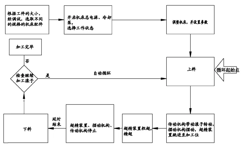
Figure 1 is a block diagram of the spherical roller outer diameter ultra precision process of the present invention;
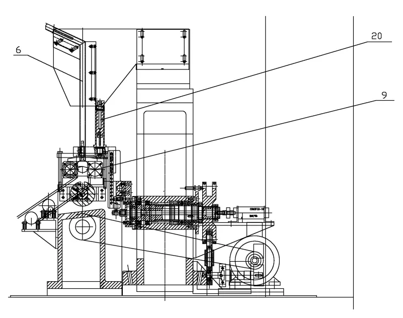
Figure 2 is a schematic diagram of the spherical roller outer diameter ultra precision machining machine tool of the present invention;

Figure 3 is a cross-sectional view of the spherical roller outer diameter ultra precision machining machine tool of the present invention;
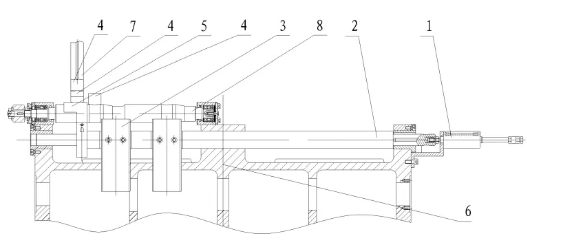
Figure 4 is a schematic diagram of the structure of the loading and unloading mechanism of the present invention;
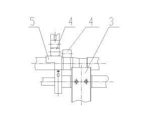
Figure 5 is a schematic diagram of the roller feeding of the present invention;
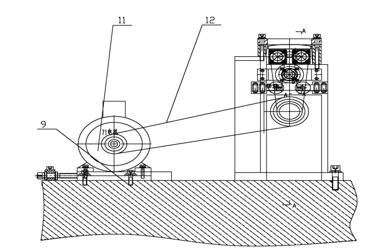
Figure 6 is a schematic diagram of the structure of the workpiece transmission mechanism of the present invention;
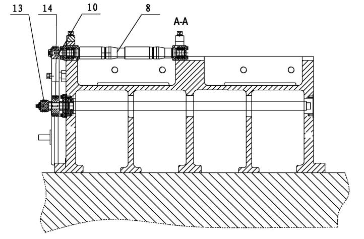
Figure 7 is a cross-sectional view of the workpiece transmission mechanism of the present invention;
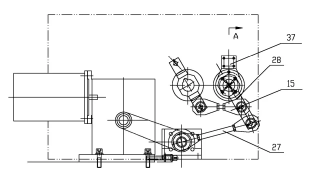
Figure 8 is a schematic diagram of the structure of the swinging mechanism of the present invention;
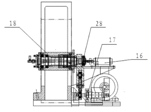
Figure 9 is a cross-sectional view of the swinging mechanism of the present invention in the A-A direction;
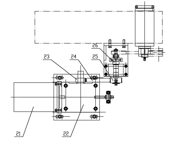
Figure 10 is a top view of the swinging mechanism of the present invention;
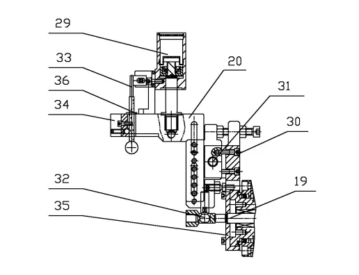
Figure 11 is a schematic diagram of the structure of the ultra precision mechanism of the present invention.
2024 June 3rd Week WBM Product Recommendation:
Precision conical drum body for commercial vehicles:
We are proud to announce that Weichuang has successfully developed high-precision tapered rollers with a production capacity of 10 million pieces per month (diameter> 13mm). In addition to this impressive production volume, we still have the remaining capacity of 4 million pieces per month. Our success is attributed to our advanced production equipment, which includes five rolling production lines and seven cold heading machines (three of which are from the United States and four are domestic). Furthermore, our heat treatment capacity is an impressive nine tons per day. At Weichuang, we strive for excellence in our production capabilities and are committed to meeting the needs of our customers.