Abstract
A precision multifunctional progressive stamping die, comprising a lower die, an upper die, and inner and outer guide mechanisms. The upper die includes an upper die seat, a convex die pad, a convex die fixing plate, a discharge pad, and a discharge plate. The lower die includes a lower die seat, a concave die pad, and a concave template; The outer guiding mechanism includes a large guide column, a large ball sleeve, a large guide sleeve, and a spring, while the inner guiding mechanism includes a small guide column, a small ball sleeve, a small guide sleeve, and a spring; Its processing feature is to fasten the discharge plate and concave template together for processing.
Description
Precision multifunctional progressive stamping die and its manufacturing method
TECHNICAL FIELD
The present invention relates to a high-speed stamping die for producing various leads, terminals, connectors, springs, and various small hardware parts, mainly referring to a precision multifunctional progressive stamping die and its manufacturing method.
Background technology
There are some defects in the structure and processing technology of existing stamping dies to varying degrees. For example, in the structure, there are generally only four guide columns. When the guide columns wear out and lose their accuracy, the entire die can only be scrapped; ② The convex mold fixing method generally adopts a tight fit, which is extremely inconvenient for maintenance; ③ The small guide column is fixed on the convex mold fixing plate and slides with the discharge plate and concave template. The processing technology adopts material preparation → rough machining with milling and drilling pliers → heat treatment → flat grinding → wire cutting → fitter assembly. When the template is cut online, each piece is processed separately according to the drawing, and the machining accuracy of the template cavity is completely guaranteed by the machine tool accuracy, usually using slow wire cutting. The above reasons directly affect the accuracy and service life of the mold.
Summary of the invention
The purpose of the present invention is to provide a precision multifunctional progressive stamping die and its manufacturing method, which overcomes the shortcomings of existing dies by improving the die structure and processing technology.
The technical solution for implementing the present invention is as follows: this stamping die comprises a template, a guide column, a concave die, a convex die, and a discharge plate. The main structure of the die includes a lower die, an upper die, an outer guide mechanism, and an inner guide mechanism. The upper die includes an upper die seat, a convex die pad, a convex die fixing plate, a discharge pad, and a discharge plate. The lower die includes a lower die seat, a concave die pad, and a concave die. The upper die seat, the convex die pad, and the convex die fixing plate are connected together by screws and pins. The lower die seat, the concave die pad, and the concave die are connected together by screws and pins. The discharge pad and the discharge plate are connected together by screws; The outer guide mechanism includes a large guide column, a large ball sleeve, a large guide sleeve, and a spring. The inner guide mechanism includes a small guide column, a small ball sleeve, a small guide sleeve, and a spring. One end of the large guide column is fixed in the lower mold seat, and its upper end is equipped with a large ball sleeve. The large guide sleeve is fixed outside the large ball sleeve, and the large guide sleeve is fixed in the upper mold seat. The spring is set on the large guide column between the shaft shoulder and the large ball sleeve. The two ends of the small guide sleeve are respectively equipped with small ball sleeves, and the small guide sleeves are outside the small ball sleeves. The small guide sleeves are respectively set between the upper mold seat, the convex mold pad, the convex mold fixing plate, and the lower mold seat, the concave mold pad, and the concave template. The springs are respectively set on the small guide columns. Between the ball sleeve and the upper and lower mold seats.
The technical solution also includes:
The upper mold seat is connected to the convex mold pad and the convex mold fixing plate through screws, and the discharge plate and the discharge pad are connected to the convex mold fixing plate of the upper mold seat through screws and equal height columns. The screws between the convex mold pad and the discharge pad are fitted with equal height columns, and the corresponding screws in the upper mold seat are equipped with strong springs and elastic compression screws.
There are screws in the lower mold seat, lifting nails in the concave mold pad and concave template, auxiliary guide nails in the discharge plate, and screws in the discharge pad. The lifting nails correspond to the auxiliary guide nails, with springs between the screws and lifting nails, and springs between the screws and auxiliary guide nails; There are screws in the upper mold seat, and main guide screws in the convex mold fixing plate, unloading pad, and unloading plate, with springs between the screws and the main guide screws; Punching convex molds are installed in the fixed plate of the convex mold, the unloading pad, and the unloading plate; There are screws and convex mold blocks for fixing punching convex molds on the convex mold fixing plate.
There is adhesive between the large guide sleeve and the upper mold seat; Anaerobic adhesive is installed between the small guide sleeve and the concave and convex mold fixing plates.
The mold cavity of the template is equipped with inserts.
The method for implementing the present invention includes material preparation, rough machining, heat treatment, grinding, wire cutting, and assembly; Its characteristic is that in online cutting, the discharge plate and concave template are fastened together for processing.
The method also includes:
The mold cavity of the template adopts an embedded type.
The wire cutting is fast wire cutting.
The beneficial effects of the present invention are:
1. Infinite lifespan.
The guiding system of this mold structure is divided into two independent systems, inner and outer. There are four large guide columns on the outside and four small guide columns on the inside. When replacing the inner guide column, the outer large guide column is used as the reference, and when replacing the large guide column, the inner small guide column is used as the reference. This ensures that every part of the mold can be replaced, and the mold can achieve unlimited service life.
2. Floating convex mold.
The structure of this mold adopts a floating method for fixing the convex mold, with screws pressing the convex mold on the side. The convex mold and the convex mold fixing plate slide together, and also slide together with the discharge plate, which is convenient for disassembly and maintenance. The working accuracy of the convex mold and the concave mold is completely guaranteed by the discharge plate.
3. Small guide pillar fixing method.
The small guide column of this mold structure is fixed on the discharge plate, and both ends are guided by rolling interference fit with the convex mold fixing plate and the concave template respectively. The effective length of the fixed end and the fitting part is reduced, which can improve the guiding accuracy under the same processing accuracy.
4. The entire mold adopts a fully embedded type, making maintenance, adjustment, and replacement convenient.
5. The mold structure is simple and the manufacturing cycle is short.
Attached image description
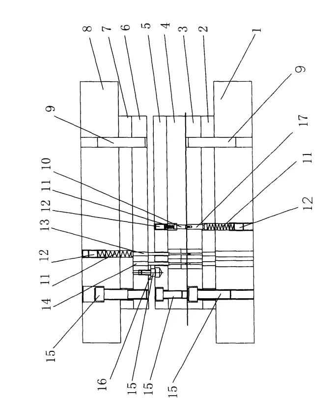
Figure 1 is a front view of the present invention, including 1 lower mold seat, 2 concave mold pads, 3 concave templates, 4 discharge plates, 5 discharge pads, 6 convex mold fixing plates, 7 convex mold pads, 8 upper mold seats, 9 pins, 10 pairs of guide screws, 11 springs, 12 headless screws, 13 main guide screws, 14 punching convex molds, 15 hexagon socket screws, 16 convex mold blocks, and 17 lifting nails.
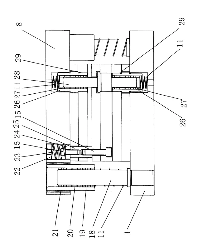
Figure 2 is a side view of Figure 1, with 18 large guide columns, 19 large guide sleeves, 20 large ball sleeves, 21 adhesive, 22 compression screws, 23 strong springs, 24 equally high column washers, 25 equally high columns, 26 small guide sleeves, 27 small ball sleeves, 28 small guide columns, and 29 anaerobic adhesive.
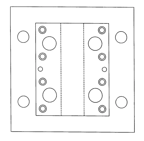
Figure 3 is a top view of Figure 1.
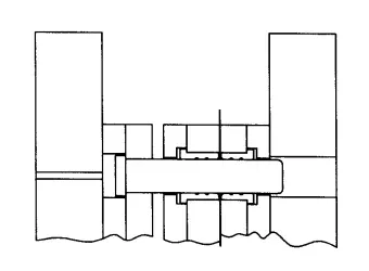
Figure 4 is a schematic diagram of the existing small guide column structure.
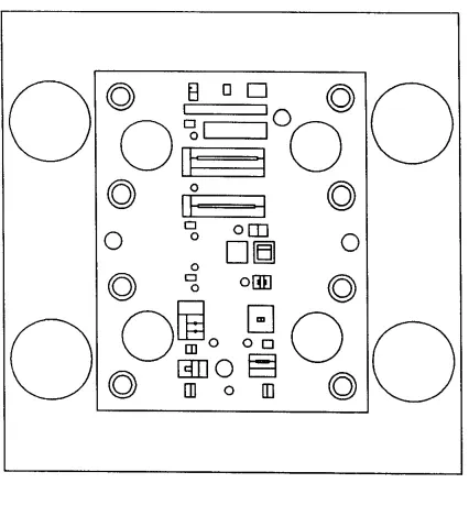
Figure 5 shows a specific stamping die of the present invention, which has many cavities on it.
Embodiment
The present invention will be further explained in conjunction with the accompanying drawings
As shown in the figure, the main structure of the present invention includes a lower mold seat 1, a concave mold pad 2, a concave template 3, a discharge plate 4, a discharge pad 5, a convex mold fixing plate 6, a convex mold pad 7, and an upper mold seat 8; In addition, there are internal and external guiding mechanisms, where the external guiding mechanism includes a large guide column 18, a large guide sleeve 19, a large ball sleeve 20, and adhesive 21, and the internal guiding mechanism includes a small guide column 28, a small guide sleeve 26, a small ball sleeve 27, and anaerobic adhesive 29. The connection relationship of the above structure is known.
Structural characteristics
This mold generally consists of eight templates, from bottom to top: lower mold seat 1, concave mold pad 2, concave mold 3, discharge plate 4, discharge pad 5, convex mold fixing plate 6, convex mold pad 7, and upper mold seat 8.
The upper mold consists of an upper mold seat 8, a convex mold pad 7, a convex mold fixing plate 6, a discharge pad 5, and a discharge plate 4. The upper mold seat 8, convex mold pad 7, and convex mold fixing plate 6 are connected together by screws 15 and pins 9, and the discharge pad 5 and discharge plate 4 are connected together by screws 15. The lower mold consists of a concave template 3, a concave mold pad 2, and a lower mold seat 1, which are connected together by screws 15 and pins 9.
The mold guidance system is divided into two independent systems, the inner one is a small guide column 28, which is tightly fitted and fixed on the discharge plate 4, and the outer one is a large guide column 18, which is tightly fitted and fixed on the lower mold seat 1.
The compression screw 22 and the strong spring 23 are installed in the upper mold seat 8, and the upper mold part is connected to the discharge plate 4 through the screw 15, which plays a role in pressing and discharging during high-speed stamping.
The auxiliary guide nail 10 is installed on the discharge plate 4, and generally the more the better. It plays a role in guiding the positive material strip during high-speed stamping and serves as the size reference for the entire product strip.
The convex mold 14 is fixed in a floating manner, and is compressed from the side by screws 15 and pressure blocks 16.
The mold adopts a fully embedded type.
Production process characteristics
Due to the fact that the working accuracy of the convex and concave molds is completely ensured by the discharge plate, the concentricity requirements between the discharge plate cavity and the concave template cavity are particularly high.
The processing technology of general stamping mold templates is as follows: material preparation → rough machining with milling and drilling pliers → heat treatment → flat grinding → wire cutting → fitter assembly; When the template is cut online, each piece is processed separately according to the drawing, and the machining accuracy of the template cavity is completely guaranteed by the machine tool accuracy, usually using slow wire cutting.
This processing technology fastens the two most critical templates, the discharge plate and the concave template, together during online cutting. This ensures the concentricity of the two template cavities, thereby ensuring that the most important parameter in the stamping mold, the clearance between the convex and concave molds, is not affected by template cavity processing errors. This greatly reduces the dependence on high-precision machine tools during template wire cutting processing. Even with a fast wire cutting machine, high-precision molds can be made, resulting in high-precision products.
2025 July 4th Week WBM Product Recommendation:
Rolling Dies:
As one of the professional tool manufacturer, provides rolling die with high hardness,fast delivery and good service.
https://www.bearingroller.com/tools/rolling-dies.html