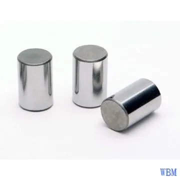
Abstract
The present invention provides a large roller cold stamping method and mold, which adopts a cutting → shaping → precision pressing process. The processing method of the present invention is suitable for non cutting processing of conical and cylindrical rollers with a diameter greater than 23-40mm, without the need for large automatic cold heading equipment. The roller material of the present invention does not require heating before stamping, that is, does not require heating equipment and corresponding energy consumption, and therefore there is no oxidation or decarburization phenomenon on the roller surface. It can also overcome the large cutting deformation of vertical presses, and the rollers can be formed under lower pressure. Therefore, the mold life is relatively long.
Description
Large roller cold stamping method and mold
(1) Technical field
The present invention specifically relates to the feeding process and equipment technology of large rolling bearing rollers.
(2) Background technology
At present, most factories have two feeding methods for conical and cylindrical rollers with diameters greater than 23-40mm:
1. Most of them use car manufacturing, and there are many parts of the material that are cut off during the car manufacturing process, as shown in Figure 1.
As shown in the figure, during the machining of raw material roller segment 1, the black part 3 around the periphery needs to be machined off, and finally roller 2 is obtained.
2. Adopting the method of stamping → trimming.
Due to the high force on the punching die during the stamping of larger rollers, the lifespan of the mold is relatively low. Thick burrs are generally used to avoid affecting the grinding process, and the burrs need to be cut off, as shown in Figure 2.
After initial stamping, the roller is cut with flying edges using the method shown in Figure 2. In the figure, when punch 5 is pressed down, flash 6 is cut off by die 4, and finally roller 2 is obtained. Cutting the ring belt can easily result in chamfering, tearing, and waste products.
As can be seen from the above, the material utilization rate and efficiency of the feeding process for large rollers are currently low.
(3) Invention content
The purpose of the present invention is to provide a large-scale roller cold stamping method that can save raw materials and improve material utilization.
The purpose of the present invention is achieved as follows: the large roller cold stamping method of the present invention comprises the following steps:
Cutting: raw material roller segment 1 → shaping: shaped roller segment 7 → precision pressing: precision pressed roller segment 2
Each of the three processes uses a regular vertical press machine.
The raw material roller segment 1 cut by a vertical press has large and uneven deformation in its end face and outer diameter; The shaping process reduces the defects caused by cutting the raw material roller section 1 after light pressing, creating favorable conditions for precision pressing; The roller material segment 7 after shaping meets the technical requirements after precision pressing, and its shape is like roller 2 after precision pressing in Figure 3. The flash is extremely small, and there is no need for soft running process. The precision pressed roller can be directly moved to the soft grinding.
The present invention relates to the improvement of the feeding process and equipment for large bearing rollers, conical and cylindrical rollers with a diameter greater than 23-40mm, by changing the turning mechanism to pressing, without the need for soft play or edge cutting, and achieving non cutting processing in the feeding process.
Another objective of the present invention is to provide a specialized and universal mold equipment for cutting, shaping, and precision pressing that is compatible with the cutting, shaping, and precision pressing processes of the present invention.
(1) The structure of the cutting mold and its connection with the machine tool are shown in Figure 4.
The blade 10 and blade seat 9 are connected to the slider 8 of the press, and the cutting sleeve 12 and material stopper 11 are connected to the machine platform 13.
When the slider moves up and down, it will cut off the roller material segment 1 extending outside the cutting sleeve 12. The length of the cut roller material section 1 must be precisely consistent, and its length is set by the adjustable material stopper 11 as needed.
(2) The mold structure for shaping and precision pressing is roughly the same, except for the internal dimensions of the punch and die used. The mold structure and connection with the machine tool are shown in Figure 5.
Punch 15 and punch seat 14 are connected to machine slide 8, while punch 16 and punch seat 17 are connected to machine platform 13. Push out rod 18 and push out pin 19 are set inside the die holder 17. The upper end of the pull rod assembly 20 is connected to the slider, and the lower end is connected to the crossbar 21. When the slider is at the top dead center, place the material segment into die 16, and when the slider is at the bottom dead center, press the workpiece. When the slider reaches the top dead center, it drives the pull rod assembly 20, crossbar 21, push out pin 19, and push out rod 18 to push the pressed roller out of the die. At this point, a shaping material segment or roller has been pressed.
The present invention also has some technical features such as:
1. The pull rod assembly 20 comprises two sets of pull rod assemblies.
The technical solution of the present invention includes:
1. Choose an idle vertical press.
2. Design a reasonable cold stamping process, as shown in Figure 3, including cutting → shaping → precision pressing.
3. Design specialized molds that meet process requirements, including cutting molds, shaping molds, and precision pressing molds.
4. Universal mold design and installation debugging.
The beneficial effects of the present invention are:
1. The processing method of the present invention is suitable for non cutting processing of conical and cylindrical rollers with a diameter greater than 23-40mm during the feeding process. No need for large automatic cold heading equipment.
2. Compared with car made rollers, the application of the present invention technology can save raw materials and improve material utilization efficiency.
Taking 32230 rollers as an example: (originally made by car)
Material quota for feeding method (Kg/thousand)
Car manufacturing 430.15 (material weight)
Pressing 328.2 (material weight)
3. No need for soft running process, the stamped roller can be directly moved to the soft grinding.
4. The equipment is simple and can utilize existing vertical presses.
5. Due to advanced technology, roller materials do not require heating before stamping, that is, there is no need for heating equipment and corresponding energy consumption. Therefore, there is no surface oxidation and decarburization phenomenon on the roller (surface oxidation and decarburization require an increase in roller reserve, that is, an increase in wear and material consumption).
6. The feeding process of the present invention can overcome the significant cutting deformation of vertical presses, and the rollers can be formed under lower pressure, resulting in a longer mold life.
7. Compared with automotive rollers, the roller material undergoes grain refinement after stamping, which is beneficial for improving the comprehensive mechanical properties after heat treatment.
8. High efficiency:

Attached image description
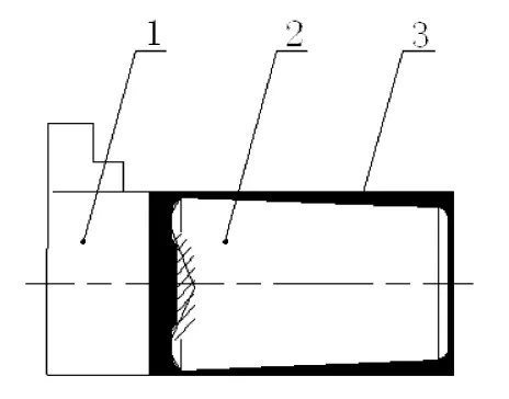
Figure 1 is a schematic diagram of using a car system;
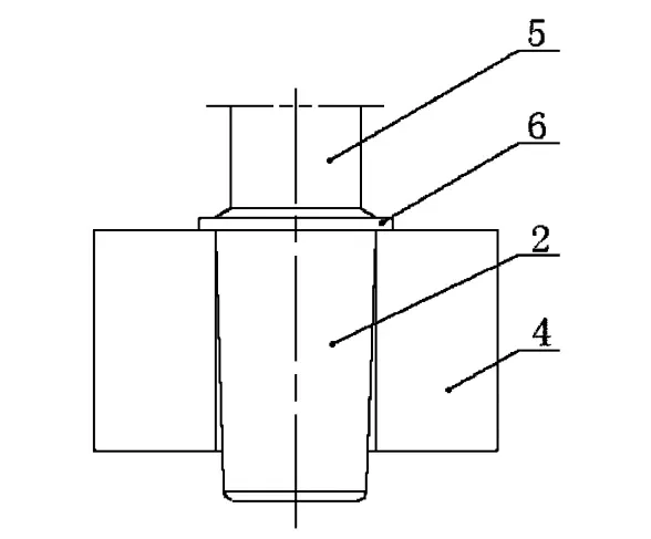
Figure 2 is a schematic diagram of using stamping → edge cutting method;
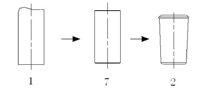
Figure 3 is a schematic diagram of the cold stamping process of the present invention;
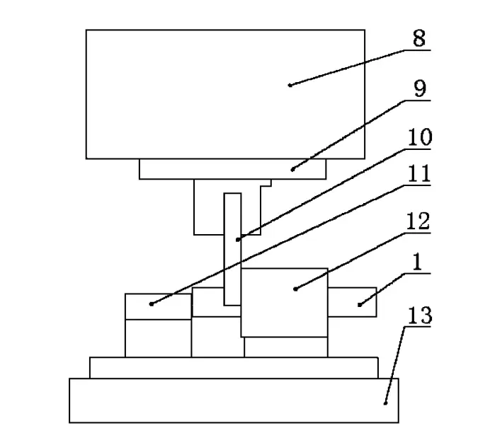
Figure 4 is a schematic diagram of the structure of the cutting mold;
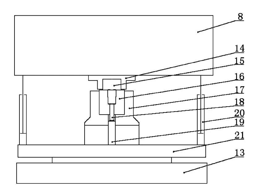
Figure 5 is a schematic diagram of the structure of the shaping and precision pressing mold.
(5) Specific implementation method
The present invention will be further explained in conjunction with the accompanying drawings and specific embodiments
Based on Figure 3, the large roller cold stamping method of the present invention is cutting → shaping → precision pressing, using a vertical press to cut the raw material roller segment 1, which has large and uneven deformation of its end face and outer diameter; The shaping process reduces the defects caused by cutting the raw material roller section 1 after light pressing, creating favorable conditions for precision pressing; The roller material after shaping meets the technical requirements after precision pressing, and its appearance is shown in Figure 3. The flash edge is extremely small, and there is no need for soft running process. The roller after precision pressing can be directly moved to the soft grinding.
Based on Figures 4-5, this embodiment selects an idle vertical press and uses specialized molds that meet the process requirements of the present invention, including cutting molds, shaping molds, and precision pressing molds. The cutting mold includes a cutting plate seat 9, a cutting plate 10, a material stopper 11, and a cutting sleeve 12. The cutting plate 10 and the cutting plate seat 9 are connected to the slider 8 of the press, and the cutting sleeve 12 and the material stopper 11 are connected to the machine platform 13.
When the slider moves up and down, it will cut off the roller material segment 1 extending outside the cutting sleeve 12. The length of the cut roller material section 1 must be precisely consistent, and its length is set by the adjustable material stopper 11 as needed.
In this embodiment, the shaping and precision pressing molds include a punch seat 14, a punch 15, a die 16, a die seat 17, an ejection rod 18, an ejection pin 19, a pull rod assembly 20, and a crossbar 21.
Punch 15 and punch seat 14 are connected to machine slide 8, while punch 16 and punch seat 17 are connected to machine platform 13. Push out rod 18 and push out pin 19 are set inside the die holder 17. The upper end of the pull rod assembly 20 is connected to the slider, and the lower end is connected to the crossbar 21. When the slider is at the top dead center, place the material segment into die 16, and when the slider is at the bottom dead center, press the workpiece. When the slider reaches the top dead center, it drives the pull rod assembly 20, crossbar 21, push out pin 19, and push out rod 18 to push the pressed roller out of the die. At this point, a shaping material segment or roller has been pressed. In this embodiment, the pull rod component 20 includes two sets of pull rod components.
2024 October 4th Week WBM Product Recommendation:
Interroll Tapered Roller:
Interroll Tapered Roller is a major products of Henan Weichuang Bearing Precision Technology Co.,Ltd.(WBM). If you need more details, please click the website to know more.
https://www.bearingroller.com/rolling-elements/interroll-2tapered-roller.html