Abstract
A medium and heavy-duty automobile flange forging process and its punching correction composite mold, belonging to the forging processing technology in the field of mechanical manufacturing, especially the automobile flange closed forging process and its punching correction composite mold. The present invention overcomes the problems of poor forging quality, multiple production processes, and low material utilization in the original production process. The closed final forging mold is used for one-time final forging forming, and the head of the mold top material rod is made into a convex platform of the mold, reducing the thickness of the connecting skin. Then, punching and correction are completed in one step on a dedicated punching correction composite mold. The punching correction composite mold consists of a correction convex mold, a concave mold, a punch, a butterfly spring, a spring pressure plate, a pull rod, etc. The mold of the present invention has low investment cost, reasonable and simple process flow, good product quality, Small processing volume, high productivity, significantly reducing product production costs.
Description
Heavy duty truck flange forging process and punching correction composite mold
TECHNICAL FIELD
The present invention belongs to the forging process in the field of mechanical manufacturing, particularly the closed die forging process for automotive flange and its punching correction composite mold.
Background technology
The flange is a key structural component in the automotive chassis system. It is an important connecting piece that connects the transmission shaft and the rear axle, playing a role in connecting and transmitting force. The forging shape is simple, and the weight of a single forging piece is basically 2-8 kilograms. Therefore, the forging methods of various forging factories are different. Currently, the representative production processes of flange forging for commercial vehicles, especially medium and heavy-duty vehicles in China, mainly include the following:
Production process of hot forging press: On a hot forging press with a tonnage of 1600T or less, the overall light pier circular bar blank is de oxidized, open type final forging is formed, and finally the edge is cut. This production process has high productivity and good forging quality, but it requires large investment, complex equipment structure, and low material utilization. This forging process is widely used in large state-owned forging factories in China.
Production process of friction press: First, remove the oxide skin from the overall light pier circular bar blank on the air hammer, then open type final forging is formed on the friction press with a tonnage of 1600T or less, and finally cut the edge. This production process has low investment, simple equipment structure, short manufacturing cycle of process equipment, but low productivity, low mold life, relatively poor forging quality, and low material utilization rate. This forging process is widely used in private forging factories in China.
Production process of forging hammer: First, the entire lightweight billet of the forging hammer with a tonnage of 3T or less is stripped of oxide skin, then the final forging is formed by opening the final forging cavity, and finally the edge is cut. This production process has low investment, simple equipment structure, and short manufacturing cycle of process equipment, but the quality of forgings is poor, the machining allowance of forgings is large, the material utilization rate is low, and energy waste is large.
Production process of free forging hammer: First, remove the oxide skin from the overall lightweight billet on a free forging hammer with a tonnage of 1T or less, and then forge it into shape through tire mold. This production process has low investment, simple equipment structure, and short manufacturing cycle of process equipment, but the quality of forgings is quite poor, the machining allowance of forgings is very large, the material utilization rate is quite low, and energy waste is large. There is a related report in the February 2002 issue of "Mechanical Management Development".
Summary of the invention
The purpose of the present invention is to overcome the problems of poor forging quality, multiple production processes, and low material utilization rate in the original production process, and to provide a medium and heavy-duty automobile flange forging process and its punching correction composite mold with high material utilization rate, low mold investment cost, high service life, good forging appearance quality, small post-processing allowance, and few forging processes.
The technical solution of the present invention is to heat the circular bar blank to the required temperature for forging process, place it on the die base working platform to remove the oxide skin, and then perform a final forging of the circular bar blank after the light pier in a closed final forging die. In this process, the closed guide part of the closed final forging die has an angle of 3 ° to 5 ° with respect to the vertical direction, a guide depth of 15mm to 25mm, an upper and lower die side gap of 0.2mm to 0.4mm, and the disc part of the forging corresponds to a mold cavity draft angle of 1 ° to 2 °. The bottom of the lower mold cavity of the closed final forging die has a top rod, and the head of the top rod is made into a convex platform of the die. The final forging is completed. The forging temperature is required to be no lower than 750 ℃. After the final forging is formed, a punching correction composite mold is used on a closed single point mechanical press to flush out the skin and continuously perform thermal correction on the warped disk part, The punching and heat correction processes are completed in one step in the punching correction composite mold.
The punching correction composite mold has a correction convex die, a concave die, and a punch. There is a spring pressure plate above the correction convex die, a butterfly spring between the correction convex die and the spring pressure plate, and an upper die seat above the spring pressure plate. The punch and the spring pressure plate are fixedly installed on the upper die seat, and the punch is located in the middle hole of the correction convex die. The pull rod is installed on the correction convex die through the through-hole of the upper die seat, connecting the correction convex die and the upper die seat. The correction convex die can move up and down relative to the upper die seat under the guidance of the pull rod. A reset spring is sleeved between the correction convex die and the upper die seat on the pull rod, and the concave die is connected to the lower die seat.
According to this process for producing flanges, the process follows the above steps. The angle between the closed guide part of the closed final forging die and the vertical direction is 3 ° to 5 °, which is greater than the draft angle of the mold cavity corresponding to 1 ° to 2 ° for the disc part of the forging. The difference in these two degrees ensures that the forging is easy to be molded. At the same time, the angle of the guide part is greater than the draft angle, which can also avoid burrs generated by the closed forging process from flowing back to the disc surface and folding. Burrs flow outward due to the large guide angle, ensuring the quality of the forging; The head of the top material rod is made into a convex platform of the mold, making the top material rod of the original process and the convex platform in the mold cavity into a whole, which has good forming strength, and thus greatly increases the depth of the cavity in the middle of the forging, reduces the thickness of the connecting skin, and is conducive to subsequent punching. According to the conventional design of the original process, the convex platform is annular with a top material hole in the middle, and there is also a top material rod in the top material hole. This annular structure with a top material hole in the middle is prone to insufficient strength of the convex platform and collapse, reducing the service life of the mold. In addition, the depth of the cavity in the middle of the forging is also very small, making the thickness of the connecting skin thick and difficult to continuously process by punching, increasing the processing steps and time, and reducing the efficiency. The punching and calibration of this process are completed in one step on the punching and calibration composite mold. The final forging is placed on the concave die of the punching and calibration composite mold. The upper die seat of the punching and calibration composite mold moves downward, and the calibration convex mold is pressed on the disc part of the forging. However, at this time, due to insufficient force and no deformation of the forging, the punch first punches open the connecting skin in the middle of the forging, which will cause deformation such as warping of the disc part. The upper die seat continues to move downward. Since the butterfly spring is in a rigid state when its force is less than the deformation resistance, the spring pressure plate will transmit force to the calibration convex mold through the butterfly spring. At this time, the calibration convex mold corrects the deformed forging. When the thickness of the disc part is within the theoretical design value and the lower limit value, When within the range, the punching correction composite mold completes punching and correction. When the thickness of the disc reaches the upper limit of the design tolerance, The butterfly spring deformation of the punching correction composite mold can meet the deformation force required for the correction disc and ensure that the closed single point mechanical press does not experience jamming during operation.
According to the design, the working load of the butterfly spring between the correction punch and the spring pressure plate is generally designed to be 20% greater than the correction pressure, which can be calculated from the mold design manual. Due to uncontrollable factors in actual production, the thickness of the disc may reach the design upper limit, which may cause the crankshaft of the closed single point mechanical press to fail to transition at the lower inflection point, resulting in equipment jamming. The butterfly spring on the punching correction composite mold can operate normally when the disc thickness is within the theoretical design value and lower limit range during calibration. When the design tolerance upper limit is reached, the butterfly spring will deform, allowing the closed single point mechanical press to complete a motion cycle and avoid equipment jamming.
The flange forgings obtained through this process can directly enter heat treatment, machining and other processes, omitting the drilling of the connecting skin and the separate calibration process, and the product quality is good and the accuracy is high.
The temperature required for forging process varies slightly depending on the material of the round bar billet, i.e. round steel, and is generally between 1150 ℃ and 1250 ℃. This temperature can be found in the forging manual.
Except for the initial temperature determined based on the material used during processing, the temperature in subsequent stages should meet the requirements of this process. When the equipment is set up properly, the process is reasonable, and the production rhythm is compact and smooth, the next process can meet the temperature requirements at the end of the previous process without the need for secondary heating.
The process flow is as follows:
1. Material cutting;
2. Heating;
3. Final forging forming, placing the round bar blank after removing the oxide skin from the light pier in a closed final forging die for forging forming;
4. Punching correction, punching off the forging skin and continuously correcting the disc part;
5. Inspection.
The main technical and economic indicators of the present invention are:
This process has low investment, high productivity, good forging quality, long mold life, and eliminates the subsequent drilling process. Suitable for the production of various types of heavy-duty truck flange forgings.
1. The precision and appearance quality of the flange forgings meet or exceed the requirements of GB12362;
2. Material utilization rate: 97-99%, which is about 85-90% of the production process of hot forging press and saves about 10% of materials. For example, producing 1 million pieces of various flanges annually saves 600T of steel and is worth nearly 3 million yuan;
3. Mold lifespan: The lifespan of the closed block mold is between 10000 and 12000 pieces;
4. Module procurement cost: A single set of insert mold is about 1.5 tons lighter than the overall mold weight. Developing 20 new product flanges annually saves 30 tons of mold steel materials, with a value of over 600000 yuan.
Due to the adoption of the block mold closed type non flash forging production process, the solid part of the mold cavity is integrated with the top material rod of the lower mold, and the punching and correction processes are carried out in the same set of composite molds and equipment. A series of technical measures and corresponding molds and equipment make the present invention not only have the characteristics of short manufacturing cycle, reasonable and simple production process flow, and easy processing, but also have the characteristics of good product quality, good appearance quality of forgings, small machining volume, and high productivity. In particular, the mold input cost and material utilization rate are significantly better than any of the original flange forging processes, while eliminating the machining and drilling process, significantly reducing product production costs.
Attached image description
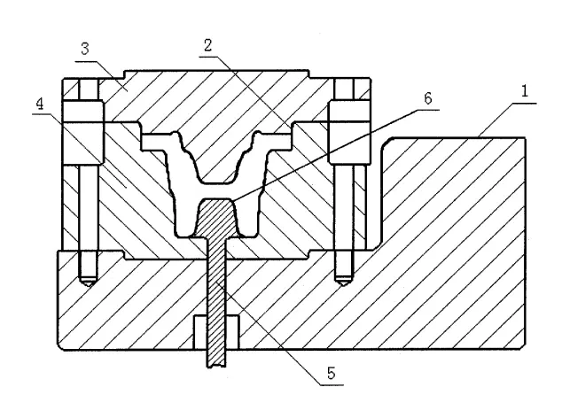
Figure 1 is a schematic sectional view of the closed final forging die of the present invention.
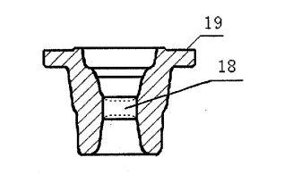
Figure 2 is a schematic sectional view of the forging of the present invention.
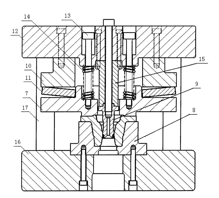
Figure 3 is a schematic diagram of the main section of the punching correction composite mold of the present invention
Embodiment
Taking the 106F type automobile flange of Dongfeng Motor Group Corporation as an example, the present invention will be explained with reference to the accompanying drawings, as shown in Figures 1, 2, and 3. The forging process flow of the flange forging is as follows:
1. Cutting: GB4025C band saw machine is used to cut round steel with a diameter of 85 and a length of 163 ± 1mm;
Due to the closed type non flash forging process we use, this process has strict requirements for the cutting quality. The cutting length of the circular bar blank must be strictly controlled, and the flatness of the end face should also be strictly controlled. To prevent the circular bar blank from being placed askew in the forging cavity, resulting in incomplete forging and local burrs.
2. Heating: KGPS300-1 medium frequency induction heating furnace is used to heat the circular bar blank to the required temperature for forging process;
3. Block die closed type non flash forging forming: A 1600T friction press is used to lightly remove the oxide skin from the heated circular bar blank on the die base working platform 1, and then the circular bar blank after the light pier is finally forged in a closed final forging die. The closed final forging die adopts a block die structure and a universal die base connection, and the final forging cavity is made into a closed structure. The angle between the closed guide part 2 and the vertical direction is 3 ° to 5 °, which is taken as 5 ° in this example, and the guide depth is 15mm to 25mm. This depth can ensure the forming quality during the non flash forging process and save the mold production cost. When the disk part 19 is relatively When the guiding depth is small, a smaller value can be taken, otherwise a larger value can be taken. The clearance between the upper and lower molds of the closed guide part 2 is 0.2mm to 0.4mm around the upper mold 3 and lower mold 4. In this example, 0.2mm is taken, and this clearance is made by the upper mold 3. The pulling angle of the mold cavity corresponding to the disk part 19 around the circumference is 1 ° to 2 °, and in this example, it is taken as 1.5 °. The bottom of the mold cavity of the lower mold 4 has a top material rod 5, and the head of the top material rod 5 is made into a convex platform 6 of the mold, that is, the top material rod 5 and the convex platform designed by the original process conventional design are made into a whole structure. This structure can effectively ensure the strength of the convex part of the mold, so that the convex part can be designed higher in the mold design and the connecting skin 18 of the forging can be thinner, and then the punching can be carried out. Reduce punching force. The draft angle of convex platform 6 is generally greater than 5 °, and the top surface of convex platform 6 is spherical or similar, which is beneficial for forging forming and easy for demolding. Figure 2 is a sectional view of the forging of the present invention, where the dashed line represents the connecting skin 18 before punching is completed. At the end of the final forging process, it is required that the forging temperature should not be lower than 750 ℃ before turning to punching correction. The above-mentioned parts involving dimensions and angles can be selected within the range of values based on the size and accuracy requirements of the forging.
4. Punching correction: JA33-500T closed single point mechanical press and dedicated punching correction composite mold are used for the correction process. Due to the crank structure characteristics of the mechanical press, this equipment is generally not used in the forging industry to complete the correction process. However, we use butterfly springs to transmit the correction pressure in the punching correction composite mold, which can ensure sufficient correction pressure to correct the deformed forgings and avoid equipment jamming during correction. The punching correction composite mold has a correction convex die 7, a concave die 8, and a punch 9. There is a spring pressure plate 10 above the correction convex die 7, a butterfly spring 11 between the correction convex die 7 and the spring pressure plate 10, and an upper die seat 12 above the spring pressure plate 10. The punch 9 and the spring pressure plate 10 are fixedly installed on the upper die seat 12, and the punch 9 is located in the middle hole of the correction convex die 7. The pull rod 13 is installed on the correction convex die 7 through the through-hole of the upper die seat 12, connecting the correction convex die 7 and the upper die seat 12. The correction convex die 7 can move up and down relative to the upper die seat 12 under the guidance of the pull rod 13. There is a reset sleeve between the correction convex die 7 and the upper die seat 12 on the pull rod 13. Spring 14, concave die 8 and lower die seat 16 are connected. The reset spring 14 adopts a cylindrical spiral compression spring to ensure that after the punching correction is completed, the upper die seat 12 drives the punch 9 to separate from the forging during the return stroke, The elastic force of the reset spring 14 is slightly smaller than the punching force, as long as it can overcome the frictional force of the punch 9 in the forging. The punching force can be calculated from the mold design manual. Due to the fact that punch 13 is a vulnerable component, punch 9 can be made in a modular form. A punch seat 15 is provided between its upper part and the upper die seat 12, and the cutting edge of punch 9 can be made of conventional overlay alloy material. To ensure the guiding accuracy of punching correction, the lower mold seat 16 is designed with a guide column 17, and the corresponding upper mold seat 12 is fitted with a guide sleeve on the guide column 17 to ensure the accuracy during up and down operation. The technical points of punch 9, guide column 17, and guide sleeve mentioned above are all carried out according to conventional design specifications. The upper die seat 12 and lower die seat 16 of the punching correction composite mold are respectively connected to the upper slider and lower pad of the closed single point mechanical press. In Figure 3, the punch 9 has already punched open the connecting skin 18 and corrected the disc part 19.
5. Inspection: Check the geometric dimensions and surface quality of the forging according to the forging drawing.
After completing all forging processes, it enters processes such as heat treatment, non-destructive testing, and machining.
In the process of mold design and forging processing, except for the special requirements mentioned above, other procedures shall be carried out in accordance with conventional design specifications, and the connection between the mold and equipment shall be carried out in accordance with conventional procedures.
2025 March 2nd Week WBM Product Recommendation:
High Chrome Steel Balls:
G5,G10,G16 Our Chrome ball usually produce according to GBT 308.1-2013 and ISO 3290-1:2014 standards. Hardness will be customized base on your requirement.
https://www.bearingroller.com/rolling-elements/steel-ball/high-chrome-steel-balls.html