Abstract: There is an inner step hole in slender shaft of high precision miniature non - magnetic bearing with shaft,and it is difficulty to clamp and locate the shaft on the electromagnetic centerless fixtureduring precisely grinding the bore. A secondary fixture is designed to solve the problem and the taper difference of the bore caused by low stiffness of slender shaft is reduced.
Key words: bearing with shaft; internal grinding; step bore; non - magnet; secondary fixture
The shaft bearing structure used in automobile engine water pumps, textile machinery, etc. is relatively simple. The shaft is a solid shaft with a diameter of more than 10 mm. It is often made of easily machinable magnetic materials such as GCr15 and G95Cr18. Generally, the bearing accuracy is P6, making it relatively easy to process. With the development of miniaturization and high precision in the fields of electronic engineering and precision engineering, the domestic bearing industry has also begun to develop high-precision micro shaft connected bearing units. The shaft diameter of this type of high-precision micro shaft connected bearing is generally below 10 mm, with an accuracy level of P4. Some bearings also have slender step holes on the shaft, and the steps require root cleaning (with a transition radius of zero or very small to avoid interference during assembly). At the same time, there are certain requirements for the taper of the inner hole of the shaft. This type of shaft connected bearing material is special (non-magnetic), small in size, and has very high precision requirements. Its slender step holes cannot be machined by general internal cylindrical grinders. Therefore, auxiliary fixtures were designed to achieve grinding processing on an electromagnetic centerless fixture internal cylindrical grinder.
1. Analysis of processing technology
The maximum outer diameter of a certain type of shaft connected bearing is 7.29mm, with a total length of 26 mm. The inner holes of the slender step are 4.2 mm × 15 mm and 3 mm × 10.4 mm. The final size and accuracy requirements of the slender shaft are shown in Figure 1.
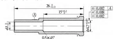
Figure 1: The dimensional accuracy of the inner hole of the slender shaft step of the shaft bearing.
If the traditional roller supported composite centerless fixture grinder (3MZ201) is used for processing, due to the small cross-sectional size of the slender shaft and poor support stiffness, the pressure of the roller type clamping tool can only be applied to one end, and the rotation accuracy of the shaft suspension end is poor. When the feed rate is large, the shaft may not rotate normally or even overturn, and the taper of the inner hole of the slender shaft step cannot meet the technical requirements; The diamagnetism of the material will prevent the workpiece from being positioned and clamped.
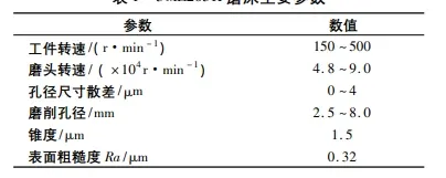
The small end hole of the slender shaft step can be ground on an electric discharge grinder due to its low requirements for shape and dimensional accuracy. The design of the large end hole on the 3MZ203K grinder (Table 1) uses electromagnetic centerless fixtures and secondary fixtures for segmented grinding, which means that the inner hole is first cut into three sections in the axial direction, ground to the specified size, and then subjected to vibration grinding and root cleaning.
Table 1 Main Parameters of 3MZ203K Grinding Machine
2. Positioning fixture design
Due to the material properties of the shaft, it cannot be adsorbed on a magnetic fixture and must be clamped by a secondary fixture that can conduct magnetism in order to perform grinding processing on an electromagnetic centerless fixture. The designed clamping and positioning fixtures are shown in Figure 2.
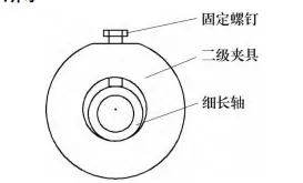
Figure 2 Schematic diagram of secondary fixture clamping slender shaft
The slender shaft is clamped with a secondary fixture and ground on a 3MZ203K dedicated grinder for manual loading and unloading. The grinding equipment and fixtures of the grinder mainly include: digital variable frequency high-speed electric spindle, digital variable frequency workpiece shaft, high rigidity hard alloy grinding wheel connecting rod, stopper plate, support plate, magnetic pole, special magnetic guide fixture, upper support, lower support, etc. The principle of grinding the inner hole of a slender shaft is shown in Figure 3.
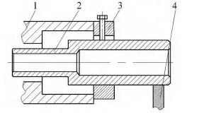
1- Magnetic pole; 2- Slender shaft; 3- Secondary fixtures; 4- Support
Figure 3 Schematic diagram of the principle of grinding the inner hole of a slender shaft
The outer diameter surface of the slender shaft is supported by both the front and rear support points. By adjusting the angle between the two supports on the semi disc and the thickness between the support points and the support seat, the slender shaft can rotate well during grinding. The positioning and installation of the secondary fixture is shown in Figure 4. The elongated shaft end surface, which has been ground, is flush with the reference end surface of the positioning block and tightly adheres to the smooth flat plate. Then, the secondary fixture is inserted to ensure that the end surface of the secondary fixture is tightly adhered to the end surface of the positioning block. Finally, the fixing nut is tightened to securely fasten the slender shaft to the secondary fixture.
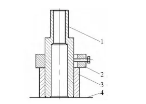
1- Slender shaft; 2- Secondary fixtures; 3- Positioning block; 4- Tablet
Figure 4 Schematic diagram of positioning and installation of secondary fixture
The outer diameter surface of the slender shaft in contact with the fulcrum serves as the reference surface for inner diameter grinding, and its accuracy directly affects the quality of inner diameter surface grinding. Therefore, the outer diameter surface of the slender shaft must be finely ground or ground to ensure that the surface roughness Ra of the outer diameter surface is not greater than 0.2 μ m and the roundness is not greater than 1 μ m; The surface roughness Ra of the end face of the positioning block and the secondary fixture should also not exceed 0.2 μ m, and the parallelism difference between the two end faces should not exceed 1 μ m. At the same time, it is necessary to ensure that the perpendicularity between the inner diameter surface of the secondary fixture and the end face is not greater than 2.5 μ m.
3. Actual production verification
According to the process requirements, the secondary fixture and positioning block were processed, and 200 samples were fixed according to the method in Figure 4. They were adjusted and processed on a 3MZ203K grinder, and the product qualification rate reached 91.5% (Table 2), which can meet the normal production needs. This indicates that the designed auxiliary fixture can meet the technical requirements when applied to the grinding of the inner hole of the slender shaft step of the micro non-magnetic shaft bearing.
Table 2 Types and quantities of product defects

4. Conclusion
For the grinding of slender step holes in non-magnetic shaft bearings, an additional secondary fixture was designed to shorten the support spacing, increase the contact area, and thereby increase the electromagnetic suction force, achieving machining on an electromagnetic centerless fixture grinder. Thin and elongated inner hole products that require root cleaning can be segmented and ground to the specified size before undergoing vibration grinding and root cleaning to avoid defects caused by factors such as grinding wheel shaft and support stiffness.
2025 June 4th Week WBM Product Recommendation:
Interroll Tapered Roller:
Interroll Tapered Roller is a major products of Henan Weichuang Bearing Precision Technology Co.,Ltd.(WBM). If you need more details, please click the website to know more.
https://www.bearingroller.com/rolling-elements/interroll-2tapered-roller.html