Abstract: The crowning of modified generatrix roller of cylindrical roller bearings for high speed railway passenger coach has been studied with the help of the finite element method. The effect of roller crowning on the contact stress and equivalent stress has been analyzed, and the optimal crowning has been determined.
Key words: bearings for high speed railway passenger coach; crowning; contact stress
1. Preface
Rolling bearings are the most widely used type of mechanical components and also one of the most vulnerable components. In the field of rail transit, rolling bearings are one of the key components for the safe operation of railway locomotives and vehicles. The condition of their operation directly affects the safety of train operation, and their failure is related to the safety of transportation. High speed has become the main direction of railway passenger transportation development in China. The maximum operating speed of high-speed passenger trains in China will reach 200km/h. Currently, the maximum operating speed of high-speed trains in Germany, France, Japan, and Spain is not less than 300km/h, and the maximum operating speed of high-speed trains has reached 350km/h. With the continuous improvement of the operating speed of railway passenger cars, high-performance high-speed passenger car bearings will be widely used, and high-speed railway passenger car bearings have become one of the key factors affecting the speed increase of railway passenger cars. Due to various factors such as design and development capabilities and manufacturing levels, the NJ (P) 3226X1 passenger car bearings produced domestically are currently only suitable for vehicles operating at speeds below 160km/h, severely restricting the normal development of the domestic high-speed railway passenger car industry. At present, high-speed railway passenger cars in China that operate at speeds above 200km/h all use imported matching bearings. To meet the needs of large-scale speed increase of railway passenger cars, it has become urgent to conduct special research on high-speed railway passenger car bearings with a speed of 200-250km/h to replace imports.
At present, the service life of cylindrical roller bearings in China is only equivalent to 1/12 to 1/8 of similar products in developed countries, and the failure rate of rollers accounts for 80% and 34.5% respectively at home and abroad. One of the main reasons is that most domestically designed rollers do not have convexity, resulting in a singular distribution of edge pressure at both ends of the roller during operation (i.e. edge effect), causing premature fatigue wear and failure at both ends of the roller. The application of convexity technology is an effective measure to change this phenomenon. Both theory and practice have shown that the geometric characteristics of the roller surface, or the type of its generatrix, have a decisive impact on its load-bearing capacity and contact fatigue life. The application of convexity technology can effectively improve the pressure distribution in the rolling contact area, reduce or eliminate pressure concentration at the edge of the roller, reduce temperature rise, and facilitate the formation of elastic fluid lubrication, thereby reducing the vibration and noise of the bearing and improving its service life. Universal bearings adopt a new structure and optimize internal design while maintaining the same external dimensions, which can significantly increase the rated dynamic and static loads of the bearings, improve their service life and dynamic performance.
Due to the increasing complexity of roller modification design, the computational load of corresponding convexity stress analysis has also sharply increased. Traditional calculation methods are no longer suitable for modern design requirements, and the contact analysis between rollers and raceways is a non static problem. It is difficult to solve the size, stress, strain, and stress and strain distribution of the contact area between rollers and raceways using Hertz theory. Therefore, it is necessary to adopt modern design methods to analyze and solve these problems, and finite element technology is undoubtedly an economically effective method.
Taking cylindrical roller bearings with circular arcs at both ends of a straight line used in high-speed trains as the research object, a simplified model was established using ANSYS simulation software, and the contact analysis method was used to quantitatively analyze the convexity of the bearing rollers. The optimal convexity of the rollers under corresponding working conditions was obtained, providing a basis for improving the contact condition between the rollers and the raceway and enhancing the bearing capacity.
2. Finite element model and simulation analysis process
The bearing is a double row cylindrical roller bearing with an inner diameter of 130mm, an outer diameter of 240mm, a roller diameter of 30mm, and a roller length of 48mm. The load is 138kN and the speed is 2100r/min. The elastic modulus and Poisson's ratio of the analyzed rollers and rings are 212 000 MPa and 0.3, respectively, with a material density of 7850 kg/m3. Based on the characteristics of rolling bearing motion, the basic assumptions in the simulation process are as follows:
(1) Due to the negligible impact of chamfers and edges on the internal stress distribution of bearings, the solid model does not include chamfers and edges.
(2) Not considering the effects of radial clearance, axial clearance, and oil film.
(3) Due to the small plastic deformation of the bearing, material nonlinearity is not considered. It is assumed that the rolling elements and inner and outer rings of the bearing are made of linear elastic materials. Due to the identical contact characteristics between the bearing rollers and raceways, based on the concept of contact mechanics and considering the structural and load characteristics of rolling bearings, a local model of the contact between the rollers and raceways can be used for overall convexity simulation analysis. Due to the fact that the contact condition between the two ends of the roller is consistent with the corresponding section in the middle of the roller, only a 1/2 model of a single roller is established, and parameterized modeling is used to save a lot of repetitive work. The solid element type selected is a three-dimensional space continuum eight node linear simplified composite element, and the contact method adopts surface contact. The contact elements are 170 and 174 elements, respectively. The mesh division near the edge contact in the z-axis direction will be relatively fine, while the mesh division in the middle part will be relatively coarse, as shown in Figure 2. This can save a lot of calculation time without affecting the accuracy of the calculation results. Figure 1 shows the schematic diagram of the modified cylindrical roller bearing and its load.
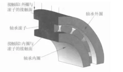
Figure 1 Schematic diagram of modified cylindrical roller bearing and its load
Constraints on the model and application of loads: (1) Symmetrical constraints on the profile. (2) Simulation of retaining frame: Partial nodes on the non-contact surface of the rolling element are subjected to displacement constraints, and the tangential UY and axial UZ displacements of these nodes are constrained in cylindrical coordinates. (3) Coupling degrees of freedom of the inner ring load surface: All nodes on the inner ring surface of the shaft are coupled with their radial UX and circumferential UY degrees of freedom. (4) Simulation of bearing seat: The outer surface of the bearing outer ring constrains all its degrees of freedom. (5) Simulation of flanges: The lateral constraints of the bearing ring and rollers restrict their displacement in the UZ direction. (6) Coupling the displacements of all nodes UX and UY on the inner surface of the inner ring in a cylindrical coordinate system. (7) Load a concentrated force in the UY direction in the Cartesian coordinate system, with the point of action at the node on the inner surface of the inner ring. (8) Create components for rollers and apply inertial loads on the rollers.
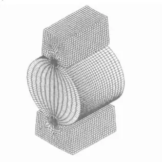
Figure 2 Mesh division diagram of the geometric model of the roller and inner and outer raceway
When solving, use appropriate time steps, set the contact stiffness and permeability to 0.3 and 0.001, respectively, and use default values for others.
3. Analysis results
According to Hertz's formula, under the same load, the contact stress between the roller and the outer ring of a cylindrical roller bearing is smaller than the contact stress between the roller and the inner ring. Therefore, only the contact between the roller and the inner ring is compared and analyzed.
In order to determine the optimal convexity measure, extensive finite element analysis was conducted to compare the effect of reducing boundary stress concentration and determine the optimal roller convexity measure. Here we will only introduce the finite element analysis results of a few representative convex measures. Figure 3 shows the distribution pattern of equivalent stress along the axial direction of the roller, and Figure 4 shows the distribution pattern of equivalent stress along the axial direction of the inner ring. The origin of the horizontal axis in Figures 3 and 4 is the point on the middle section of the roller generatrix, and the right end is the point on the end of the roller generatrix; And 1, 2, 3, 4, 5, and 6 respectively represent the convex metric roller bearings corresponding to the numbers in Table 1. Table 1 lists the main results of finite element analysis for each convexity metric. When the convexity metric is zero, that is, for a non modified ordinary straight line roller bearing, the stress reduction rates in the table are relative to the non modified straight line roller.
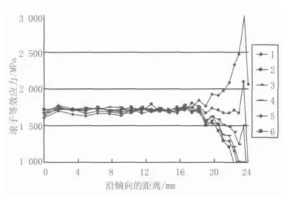
Figure 3 Distribution law of equivalent stress of roller along the axial direction
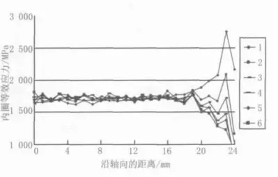
Figure 4 Distribution law of equivalent stress along the axial direction in the inner ring
Table 1 Main Results of Finite Element Analysis
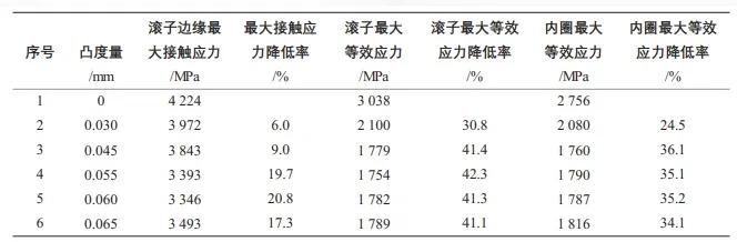
As shown in Figure 3, the distribution pattern of each curve along the axial direction of the roller is basically similar. The stress distribution in the middle of the roller is relatively uniform, and the stress at the end of the roller increases significantly, resulting in boundary stress concentration. From the stress values, the middle stress of the non modified roller with a convexity of 0 is the smallest among all curves, and the edge stress at the end is the largest, indicating that the "edge effect" is the most severe. The stress of curve 3 with a convexity of 0.045 is slightly higher in the middle of the roller than that with a convexity of 0, but the stress at its edges is greatly reduced. The distribution pattern of other curves is completely similar to that of curve 3.
From Figures 3 and 4, it can be seen that the distribution pattern of equivalent stress along the axis of the roller and inner ring is basically similar, with boundary stress concentration occurring at the edge of the roller, while stress distribution in other areas is relatively gentle, and there is a slight rise at the intersection of the roller straight line and the modified arc. According to the analysis of equivalent stress, the best bearing capacity of the roller is 0.055mm. Figure 5 shows the stress contour map of the roller with a convexity of 0.055mm. The reduction rate of the maximum contact stress and maximum equivalent stress relative to the non modified roller at each convex measurement is shown in Table 1.
4. Conclusion
In summary, from a theoretical analysis perspective, the optimal modification convexity of the modified roller bearing under the studied load is 0.055mm. Therefore, in order to reduce the degree of boundary stress concentration, the convexity should be made as close to 0.055mm as possible under the conditions of allowable processing capacity.
2025 June 3rd Week WBM Product Recommendation:
Super finishing roll:
We have 30 years in designing and producing experience in bearings rolling elements and tooling industry with ISO9001 and IATF16949.Tooling for cold heading machine,lathe,grinder will be produced accoriding to your requirement.