Abstract: The heavy punching cold-forging die for the conical-roller of bearing made of Cr12MoV steel has shorter service life. The failure of this die is mainly due to the heavy wear of the mould cavity, longitudinal and transversal expansion fracture, denting round corner, and appearance of fatigue erosion pit. Based on the fundaments of plastic deformation, jiggle wear, and fatigue fracture, the Author analyzed the failure mechanisms of slight plastic deformation, squeezing wear, and squeezing expansion fracture during working. It is concluded that the improvement way to prolong the service life is to adopt the new die materials such as hard alloys and the new high strength and toughness cold work die according to the die design and service conditions. Key words: cold-forging die; failure mechanism; improvement way
1. Introduction
GCr15 steel bearing tapered rollers are formed by cold heading, also known as cold stamping. At present, Cr12MoV steel is mainly used as the forming mould in China. Due to the heavy stamping force exerted on the mould during the stamping process, its service life is relatively short. In the early days, Cr12MoV steel moulds were quenched at 1080 ℃ and tempered at 520 ℃, with a hardness of 62~64HRC. Due to the large size and uneven distribution of carbides in this steel, the phenomenon of fracture and collapse is more severe during use. In recent years, many factories have switched to the treatment process of 1040 ℃ quenching and medium temperature tempering, with a hardness of 60-62HRC and an increase in impact toughness. The fracture phenomenon has been greatly reduced, and the service life has been increased by about twice. Taking the 18mm tapered roller as an example, originally it could only punch 1700-2000 pieces, but now it can punch over 4000 pieces, with a maximum of 10000 to 20000 pieces. However, it still belongs to short-lived moulds, which not only increases mould consumption, but more importantly, affects production efficiency. Due to the fact that the tapered roller material is GCr15 steel with a relatively high hardness (197-227HB), it is upset from a cylindrical shape to a conical shape after stamping, and the upper and lower ends are flat bottomed and stamped into a circular arc shape, causing the surface of the mould cavity to momentarily withstand heavy load impact and friction forces locally. According to the punching pressure, it can reach over 3000MPa. The problem of low service life of Cr12MoV steel moulds is difficult to solve. Therefore, the domestic bearing industry is actively researching new mould materials.
The main manifestations of mould failure are changes in the size of the roller blank and whether cold heading processing can proceed normally. If the size of the roller blank becomes larger, or even the blank is not filled enough (called under pressure), or if the roller blank is deformed or even unable to be stamped due to mould cracks or cavity defects, the mould becomes invalid and scrapped, and a new mould needs to be replaced. It is generally believed that the increase in cavity size is mainly caused by insufficient wear resistance of the mould, while cracks, collapses, and internal surface defects are mainly caused by insufficient toughness. However, the problem is not so simple because under heavy impact force, in addition to strong friction and wear, there is also accompanied by microplastic deformation, both of which can cause the mould cavity size to increase. Mould fracture also exhibits fatigue fracture characteristics, which are related to both brittleness and the generation and development process of crack sources. The generation of internal defects in the mould cavity is also related to plastic deformation and fatigue fracture.
2. Failure forms and force analysis
After investigating the existing moulds of Cr12MoV steel in a certain factory, it has been found that there are five main situations of ultimate failure, as shown in Figure 1: ① The mould cavity size becomes larger, exceeding the allowable error range, causing the size of the conical roller blank to exceed the tolerance, and even insufficient filling, resulting in under pressure, accounting for about 60%; ② The development of longitudinal cracks in the mould results in cracks on the inner wall of the mould cavity, which is called expansion cracks, accounting for about 20%; ③ Circular fracture of the mould mainly occurs on individual moulds, accounting for about 5%. For most split moulds, this fracture generally does not occur; ④ Fillet collapse or fatigue pits, accounting for approximately 10%; ⑤ Other cracks, such as material withdrawal or surface cracks, account for approximately 5%.
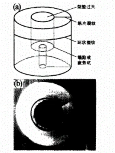
Fig.1(a)failure form and position of the die
(b)photo of expansion fracture die
During the cold heading process of conical roller forming, the stress situation of the mould is shown in Figure 2. The inner wall of the mould is subjected to the squeezing force P, which forms a shear stress t. The magnitude of the shear stress is related to the friction force, and the distribution from the surface to the inside gradually changes, with a peak value on the inner surface.
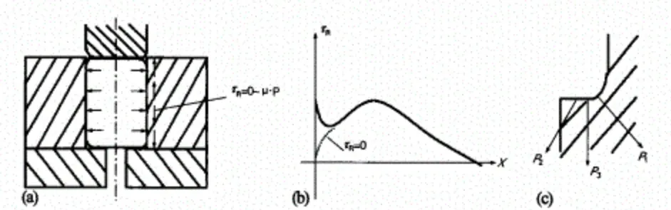
Fig.2 Scheme of the forces distribution of the cold-forging die.
(a) the circular shearing stress (b) the distribution of shearing stress in working surface layer (c) the forces on the round corner
The first situation of mould failure is caused by two reasons: wear and plastic deformation. During stamping, the workpiece is subjected to instantaneous extrusion deformation, which first occurs at the surface of the slightly convex body. Although the surface is very smooth, there is always a certain roughness on the inner surface of the new mould, that is, there are micro uneven bumps. When the pressure reaches 1000-3000MPa, the stress is greater at the slightly convex body, leading to local plastic deformation and significant shear stress at a certain depth. Due to the squeezing effect, there is a slight relative displacement between the workpiece and the surface of the mould, which is similar to fretting wear. Due to the high positive pressure, the billet of the processed roller repeatedly strongly rubs against the inner surface of the mould, causing wear. Due to the squeezing effect, the mould cavity is also subjected to expansion force. When the workpiece comes into local contact with the mould surface, the uneven force can exceed the yield strength of Cr12MoV steel, resulting in microplastic deformation and an increase in the size of the mould cavity. The annular depression in Figure 1b is caused by plastic deformation on the contact surface of the split mould.
In addition, the heat transformed by the deformation of the processed rollers and the heat generated by strong friction can locally increase the surface temperature of the mould cavity, causing instability in the surface structure of the mould cavity and making it more prone to plastic deformation and wear.
The second and third cases of mould failure, due to the repeated action of circumferential force, result in local initiation of cracks, and the crack source often occurs at the surface layer of blocky carbides or inclusions. Once cracks occur, due to stress concentration, the crack propagation here is accelerated, ultimately leading to brittle fracture. Figure 3 shows the schematic diagram of longitudinal crack development and fracture photos. Observing the fracture photos, the crack source appears as a circular corrosion pit. The crack source may be formed by the peeling of large carbides or inclusions, which are more likely to adhere or bite with the workpiece after formation, causing the crack source to expand. With the action of alternating impact force, cracks develop in both vertical and horizontal directions. The appearance of cracks releases the circumferential force, while new cracks no longer appear in other positions. Therefore, only one crack occurs in a mould. The fracture morphology exhibits quasi cleavage characteristics, and the fracture surface exhibits fatigue fracture characteristics. Moreover, due to the uneven circumferential force on the mould, it causes uneven deformation and expansion of the upper and lower parts, leading to the initiation and propagation of transverse cracks. Transverse cracks are also related to uneven cooling of the mould during heat treatment.
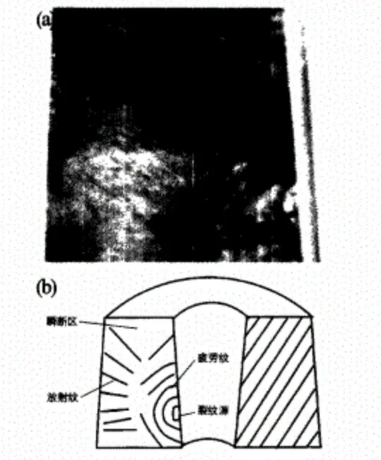
Fig. 3(a) Photo of the fracture die and (b) sketch of the fatigue cracks propagation
The fourth case of mould failure is due to the instantaneous concentration of compressive stress at the rounded corner, up to 3000-4000MPa, causing a certain depth (about a few) below the surface at that point μ Within m, significant shear stress is generated, causing the material to yield and forming a plastic deformation zone. Under repeated stress, microcracks parallel to the surface are generated, ultimately exhibiting collapse and contact fatigue pitting.
The fifth situation is essentially similar to ②, ③, or ④, except that the location where fatigue fracture and collapse occur is different. According to the analysis of failure forms, the main failure mechanisms are microplastic deformation, fretting wear, and fatigue fracture.
The microplastic deformation mechanism is also caused by dislocation slip. Does deformation begin with the nucleation of new dislocations or with the activation of existing dislocations? There are two views. The first one suggests that plastic deformation is initially related to the nucleation of new dislocations, which can form on small steps of single atoms, grain boundaries, subgrain boundaries, etc. on the surface; The second viewpoint suggests that the initial stage of plastic deformation is due to the activation of upper dislocation sources at grain boundaries [1]. Therefore, the surface layer of the mould prioritizes the occurrence of dislocation slip, causing microplastic deformation, which gradually propagates to the interior. In order to improve the resistance to microplastic deformation, it is actually necessary to create obstacles to the movement of all dislocations. Firstly, it is necessary to increase the frictional resistance of the lattice. The effective alloying of the solid solution can improve the lattice resistance of dislocation movement. Different alloying elements have different effects on the strength of the matrix. Si, W, Cr, Mo, V, etc. are all effective strengthening elements, especially Si and W, which can significantly improve the yield strength. Research has shown that there is an elastic threshold value for the elastic limit, below which dislocation slip cannot be initiated. Therefore, increasing the yield strength of materials can effectively improve the deformation resistance energy, especially when the maximum impact pressure is constant. Refining the grain size and martensitic transformation substructure can both increase dislocation density and enhance the degree of pinning. On the other hand, during the refinement of hard carbonized material points, dislocations form dislocation rings around a series of particles. When the particles are highly dispersed, the resistance to microplastic deformation is maximum.
Micro wear is mainly similar to adhesive wear in the initial stage. The relative motion between the workpiece and the mould surface is reciprocating. After repeatedly breaking the cold solder joints of the micro convex body, the adhesive tendency gradually decreases and finally transitions to a stable stage. In the steady-state stage, both adhesion and abrasive wear mechanisms play a role, resulting in delamination wear on the surface. In general, the higher the hardness of tempered martensite and carbide in the mould matrix, the stronger the wear resistance. In addition, although in the case of sliding wear, especially in the presence of abrasive particles, when the size of carbide particles is large, they can be firmly embedded in the matrix to play a greater role. However, under cold stamping conditions, the peeling speed of small-sized carbides due to extrusion is relatively small, and the wear amount is largely determined by the volume fraction and hardness of carbides. The larger the volume fraction of carbides, the higher the hardness, and the smaller the wear amount.
The crack source of brittle fracture and fatigue crack is preferentially generated on macroscopic defects, and coarse carbides or inclusions in Cr12MoV steel may be the initiation site of the crack source. The crack propagation speed is related to the strength and toughness of tempered martensite, as well as to the size of carbides. The smaller the size of carbides, the higher the fracture toughness of the material, and the slower the crack propagation speed.
Finally, it should be mentioned that the heat generated during the stamping process increases the surface temperature of the mould, which strengthens the thermal activation process, relaxes the dislocation pinning, and even reduces the hardness of the matrix, increases wear and plastic deformation. Therefore, new materials should also have good resistance to rebound.
4. Application of New Mould Materials
According to failure analysis, there are four main requirements for the microstructure and performance of mould materials: ① high plastic deformation resistance, ② high wear resistance, ③ high fatigue fracture resistance, and ④ for new steel applications, it is necessary to choose cold work mould steel with refined carbides, high volume fraction ratio, and high hardness.
For small-sized tapered rollers, it is reasonable to use a hard alloy mould. Due to the ultra-high hardness and high elastic modulus of hard alloy, it has high wear resistance and plastic deformation resistance, which can ensure the accuracy of the processed parts. The service life can reach 10-20 times that of the original Cr12MoV steel mould. For large-sized tapered rollers, the stamping machine tool can reach 160-250 tons, and the use of hard alloy moulds can cause premature failure due to brittle fracture. The increase in service life is insufficient to offset the increase in cost. Therefore, it is necessary to study new high-strength and toughness cold working die steels.
We have calculated the composition of a new type of high-strength and ductile die steel DM9 based on phase equilibrium thermodynamics. After melting, forging, rolling, heat treatment, microstructure, and performance studies, it has been found that there are five types of carbides, M3C, M6C, M23C6, M7C3, and MC, in the annealed state of the steel. Due to the thermodynamic and kinetic differences in the nucleation, growth, and dissolution of different types of carbides in austenite, the carbides can be uniformly refined, with an average size of 0.66 after annealing μ m. Average size of remaining carbide after quenching 0.5 μ m. It is 1/8-1/10 of the remaining carbide size of Cr12MoV steel. Due to the addition of Si and W in addition to Cr, Mo, and V in the martensitic solid solution strengthening elements of DM9 steel, the yield limit is increased compared to Cr12MoV. Moreover, after heat treatment, there are more high hardness carbides M6C and MC, and their wear resistance is also high. This steel is applied to large-sized conical roller moulds, and its service life is more than 2-3 times that of the original Cr12MoV steel.
During the quenching and heating process, M3C and M23C6 of DM9 steel are more easily soluble in austenite, which can effectively improve the solid solubility of austenite at lower quenching temperatures. However, the large amount of undissolved M6C and VC can effectively hinder grain growth. Therefore, this steel can be used for medium temperature quenching and low temperature tempering, and its technical performance and usage effect are better than Cr12MoV steel.
2023 November 4th week WBM Product Recommendation:
High Chrome Steel Balls:
G5,G10,G16 Our Chrome ball usually produce according to GBT 308.1-2013 and ISO 3290-1:2014 standards. Hardness will be customized base on your requirement.
https://www.bearingroller.com/rolling-elements/steel-ball/high-chrome-steel-balls.html