
Abstract: Two of the bearing rollers which were made of G20Cr2Ni4A steel with carburizing + quenching + three times of tempering, fractured during the running process. The causes of the fracture were analyzed through the fracture position, morphology, microstructure, phase composition and residual austenite, The results show that the main reason of the fracture of the roller is the inner surface oxidation, which makes the steel's anti fatigue property worse, leading to the crack initiating in stress concentration point and the final fracture.
A certain bearing company uses G20Cr2Ni4A steel to produce large bearings for steel rolling equipment. The shape diagram of the bearings and rollers is shown in Figure 1. One set of bearings has 150 rollers, and the technical requirement is that the rollers need to be ground after deep carburizing 6 ~ 0. 8 mm, After grinding, the depth of the infiltration layer should be greater than 2 5 mm. The processing route is bar material → fine forging of bar material → rough turning → ultrasonic testing → fine turning → deep carburizing (930 ℃× 60 h) → high temperature quenching (880-900 ℃, insulation for 2 h) → high temperature tempering (650 ℃× 8 h) → re quenching (800-820 ℃× 2 h) → tempering (150 ℃) → rough grinding → additional tempering (150 ℃) → fine grinding → fine grinding → magnetic particle testing → ultra precision → grouping. During use, two out of 150 rollers in a set of bearings broke. Request an analysis of the cause of failure.
1. Experimental methods and analysis
1.1 Observation of macroscopic fracture morphology
Figures 2 (a) and (b) show the macroscopic fracture morphology of the failed roller. From the fracture morphology in Figure 2 (a), it can be seen that the fracture of the bearing roller belongs to a typical contact fatigue failure. The fracture surface has obvious and smooth grain lines distributed at the step, which is an important characteristic of fatigue fracture. Fatigue sources usually appear on the surface of components and are located at the center point of the fatigue arc. From Figure 2 (a), it can be seen that the damaged rollers first generate fatigue sources in the inner hole, as shown in Figure A, and then propagate radially along the rollers. After the cracks propagate to the outer surface, they rapidly propagate along the axial direction, causing the rollers to fracture. From the direction of fatigue source propagation, it can be seen that cracks propagate under the action of axial force perpendicular to the inner hole of the roller. The fatigue source is located at the step of the inner hole of the roller. Due to stress concentration at the step, the fatigue source should be generated at the location of maximum stress. In addition, for the fractured roller, the shape of the steps on both sides is different. The distance from the end face to the deepest part of the step on one side is about 5 mm (end A), while the depth on the other side is only about 2 mm. The fatigue source appeared at a step depth of 5 mm, and another piece provided by the manufacturer was tested under the same conditions without a broken roller, with a depth of about 3 mm, indicating that the shape of the step may have some influence on the fracture.
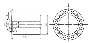
Fig.1 Schematic of the roller and bearing
From the analysis of Figure 2 (b), it can be seen that the roller broke into multiple pieces. According to the analysis of the two fragments provided, these two fragments basically constitute half of the cylindrical roller, so it is estimated that the roller has broken into four pieces, indicating that multiple fatigue sources have formed during the service of the roller. Due to the fact that the fatigue sources are all located at the step, it is unlikely that they are affected by metallurgical defects, inclusions, or other factors. Instead, it is likely that multiple fatigue sources are formed simultaneously in the inner hole due to the unacceptable stress values of the material structure at this step, leading to the propagation of fracture. Based on the macroscopic fracture morphology, the following conclusions can be preliminarily analyzed: there are two reasons for roller failure: one is that the internal structure is unqualified and forms a fatigue source, and the other is that the work overload generates undue stress and causes fatigue failure. Therefore, in-depth analysis of the internal structure is needed.
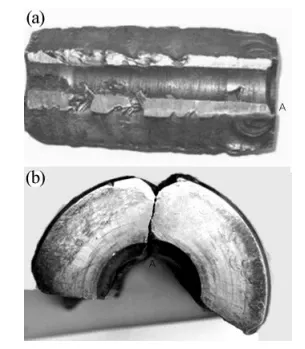
Fig.2 Fracture appearance of the broken roller
1.2 Composition inspection and microstructure observation
The composition of the damaged roller was tested using a spark direct reading spectrometer (OBLF QSN 750), and compared with the GB/T 18254-2002 "High Carbon Chromium Bearing Steel" standard. The results are shown in Table 1. From the composition inspection results in Table 1, it can be seen that the roller material G20Cr2Ni4A steel meets the requirements of GB/T 18254-2002 standard, indicating that the roller fracture failure is not a problem with the raw material. Therefore, samples were taken from the inner hole and outer surface near the fracture surface of the fractured roller for microstructure analysis, and the results are shown in Figure 3 (a) and (b). In order to better compare and observe, samples were taken from the same position on the rollers that were not broken for analysis, as shown in Figure 4 (a~d).

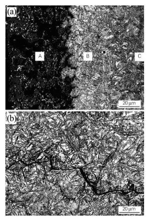
Fig.3 Microstructure of the broken roller on inner wall ( a) and external surface ( b)
Comparing Figure 3 and Figure 4, it can be seen that the microstructure of the fractured bearing roller is completely different from that of the roller without fracture. There is a layer of abnormal structure on the surface of the inner hole of the fractured roller, as shown in Figure 3 (a) A, this layer of structure is completely not the structure obtained after carburizing and quenching. The matrix is a layer of gray black structure, with some white particles distributed on it. There are also some holes in the gray structure. Below this layer of structure is mainly the mixed structure of acicular martensite and Flat noodles martensite, and there is a certain amount of residual austenite, as shown in Point B. The central structure is Flat noodles martensite+retained austenite, see point C.
From Figure 3 (b), it can be inferred that the microstructure of the outer surface of the fractured roller is not the normal structure after carburizing and quenching. There are a large number of coarse needle like martensite and residual austenite areas on its surface. Although no peeling phenomenon was observed on the outer surface of the roller with the naked eye, cracks were observed in the microstructure on the outer surface of the roller, and some cracks extended along the grain boundaries. It can be concluded that even if the roller does not break, its outer surface will still experience peeling.
Under the same material and process conditions, the surface of the normal roller inner hole is the normal structure after carburization. The structure of the inner hole surface is as shown in Figure 4 (a), which is a mixed structure of fine Flat noodles martensite+carbide+retained austenite (a small amount of bainite structure). There is no black gray structure similar to the inner surface of the broken roller hole. The central structure is Flat noodles martensite+lower bainite+retained austenite, as shown in Fig. 4 (b). The surface structure of normal roller excircle is shown in Figure 4 (c), which is fine Flat noodles martensite+lower bainite+retained austenite. There is also lower bainite+Flat noodles martensite structure in the center, as shown in Figure 4 (d). Therefore, the heat treatment process of normal rollers may be different from that of damaged rollers, and from the perspective of microstructure analysis, normal rollers should have undergone isothermal quenching treatment. According to metallographic analysis, the following conclusion can be drawn: the black gray structure in the fractured roller is the key cause of the formation of multiple fatigue sources in the inner hole, leading to fatigue fracture. Therefore, structural analysis of this layer of structure is needed.
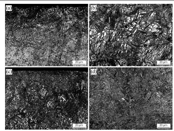
Fig.4 Microstructure of the normal roller on the inner wall and external surface ( a) inner wall; ( b) core in inner wall; ( c) external surface; ( d) external subsurface
1.3 XRD analysis and determination of residual austenite
Metallographic analysis shows that there is an abnormal structure on the inner surface of the fractured roller. The structure of this layer was analyzed using a Philips X'pert PRO SUPER X-ray diffractometer, and the results are shown in Figure 5.
From Figure 5, it can be seen that the main phases on the inner surface of the fractured roller are iron, iron chromium, and iron nickel oxides, indicating that the abnormal structure has undergone severe oxidation of the roller during carburizing or quenching. Due to the grinding process on the outer surface, no oxide was observed, while the inner hole surface was not reworked to retain the oxide. Additionally, the contact fatigue performance of bearing steel is highly sensitive to small defects in the steel, with oxide being the most harmful. It can be seen that the presence of this oxide is a key factor in the formation of fatigue cracks.
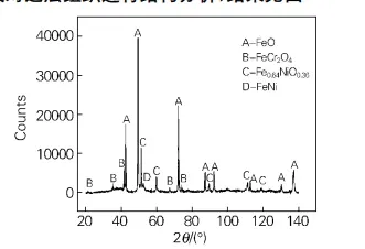
Fig.5 X-ray diffraction pattern of the fractured roller in inner wall surface
It can be clearly seen from Figure 3 (b) that there is a large amount of residual austenite on the outer surface of the damaged roller. The residual austenite content of the roller was determined by XRD, and the results are shown in Figure 6.
From Figure 6, it can be seen that the fractured roller has a significant amount of residual austenite. Figure 6 (a) shows that the measured amount of residual austenite on the outer surface is 8 57% and Figure 6 (b) show that the amount of residual austenite measured on the parallel axis grinding surface (metallographic sample grinding surface) is 19 97%. The presence of a large amount of residual austenite can reduce the mechanical properties such as hardness of the roller, making it more prone to failure under high cross strain stress. In addition, the difference in the amount of residual austenite between the surface layer of the roller and the metallographic grinding surface indicates uneven microstructure and the presence of structural defects.
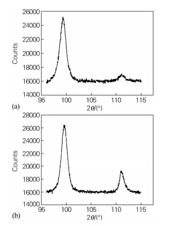
Fig.6 X-ray diffraction patterns of retained austenite in the fractured roller ( a) external surface of roller; ( b) inner wall surface of roller
2. Discussion and Analysis
Macro analysis shows that roller failure belongs to fatigue failure. The destruction process: Firstly, multiple fatigue crack sources are generated at the step on one side of the inner hole, and the fatigue source is the location with the highest axial load. After the formation of the fatigue source, it first expands radially along the roller. After the crack extends to the outer surface, multiple through cracks are formed, which rapidly propagate along the axial direction and ultimately cause the roller to fracture. Due to the fact that several fatigue sources are located on the same side of the steps, it is impossible for metallurgical defects, inclusions, or other factors to affect them. This is because the probability of metallurgical defects such as inclusions occurring at the same step is basically zero. Therefore, there are two most likely reasons for the fracture: one is that the bearing is subjected to undue external forces during use (overload, stress concentration, excessive residual stress, etc.); The second reason is that the internal structure of the roller did not meet the standard requirements. After analysis, this is the main reason.
According to the standard requirements, the normal structure of the roller surface should be hidden needle martensite+fine carbide+a small amount of retained austenite, and the center should be Flat noodles martensite. Metallographic analysis shows that the microstructure of the inner hole surface of the fractured bearing roller is not of this kind, and there is a layer of black gray on the inner surface, which is the main reason for the multiple fatigue sources of the bearing roller. According to XRD analysis, the microstructure of the black gray layer is composed of oxides of iron, iron chromium, and iron nickel. This oxide layer cannot withstand fatigue loads under bearing service conditions. Therefore, when the roller is subjected to alternating loads, a fatigue source is formed at the point of maximum stress (step), followed by expansion and fracture. This layer of oxide should have been generated during quenching or carburizing processes. The outer surface of the roller should also undergo oxidation, but after grinding, no oxide layer was observed under the metallographic microscope, and the inner hole was not processed to retain the oxide layer.
There are a large number of coarse martensite and residual austenite on the outer surface of the roller. XRD analysis shows that the amount of residual austenite reaches about 20% and microcracks have been found, indicating that even if the roller does not fracture, surface peeling will definitely occur after continued use for a period of time. The formation of coarse martensite may be due to overheating during heating and quenching, as well as mixed crystal phenomena caused by segregation of raw material composition and banded structure. In addition, there are two problems with the processing of rollers: 1) The surface of the inner hole of the roller is subjected to alternating tensile stress. To avoid fatigue damage, the inner hole should have a low roughness. The drawing requires an inner hole roughness of 1 6. The roughness of the inner surface of the damaged roller is significantly too high. 2) The shape of the steps at both ends of the fractured roller is different, and the fatigue source appears at a step depth of 5 mm. Therefore, the shape of the roller step may also have some influence on the fracture. To clarify this issue, precise mechanical calculations are needed.
3. Conclusion and Suggestions
The fracture of bearing rollers belongs to fatigue fracture, which is caused by severe oxidation on the surface during carburizing or subsequent quenching process. The oxide layer cannot withstand the alternating load under the service conditions of the bearing, forming a fatigue source in the inner hole oxide layer. There is a large amount of coarse martensite and about 20% residual austenite on the outer surface, which is an abnormal structure, and microcracks have been found on the outer surface. Based on the above analysis results, the following improvement suggestions are proposed: 1) Strictly control the carburizing and quenching heating temperatures, especially the second quenching heating temperature; Temperature uniformity testing of the furnace and prevention of oxidation during quenching. For quenching equipment after deep carburizing, JB/T 8929-1999 "Deep carburizing" standard has strict regulations: the temperature uniformity of quenching equipment is less than 10 ℃; A controllable protective atmosphere must be provided. 2) Check if any inappropriate substances are mixed into the carburizing medium to prevent oxidation during the carburizing process. 3) Cold treatment of bearings can be considered to improve the roughness of roller inner hole machining and enhance the step shape. After adopting the above suggestions, the rollers did not break during use.
2025 May 4th Week WBM Product Recommendation:
Cutter:
WBM produces taper roller dies with high efficiency and automation. Rollers are formed on a single automatic cold heading press and are fed, cut, and punched into the die for five steps.
We can produce different types and sizes taper roller dies with quality assurance,include:Combination Punch,Outside Sleeve,Blade,Combination Punch,Feed Cylinder,Combination Dies,Double Layer Sleeve,Insert.
