Abstract
The present invention discloses a distributed extrusion process method. After heating the refined steel ingot to 1050-1250 degrees, the steel ingot riser is cut off, and then the steel ingot is upsetting. The center hole is pressed on the upsetting steel ingot, and the first perforation needle presses the steel ingot downwards along the center hole of the steel ingot plane to heat pierce the steel ingot. The steel ingot is fixed and placed in a prestressed extrusion cylinder, and the extrusion head of the extrusion shaft presses the metal downwards along the center hole of the steel ingot at different angles to achieve distributed extrusion of the steel ingot. When the upper end face of the steel ingot tends to be flat, the steel ingot is then refined with a precision extrusion shaft to make the wall thickness of the steel ingot shell uniform; The upper end of the extrusion head with a cross-sectional area smaller than that of the extrusion shaft is fixed at the lower end of the extrusion shaft, and the center of the prestressed extrusion cylinder, extrusion shaft, and extrusion head are aligned. The prestressed extrusion cylinder is a barrel shaped column with an inner diameter of the upper opening greater than the outer diameter of the extrusion shaft and extrusion head. The shell made of the present invention has a uniform wall thickness, no defects such as cracks, and high reliability and strength.
Description
Distributed Extrusion Process Method and Its Distributed Extrusion Mold
technical field
The present invention relates to a metal processing method and its related molds, particularly to a distributed extrusion process method and its distributed extrusion molds.
Background technology
The development of nuclear power has been elevated to the top of national strategic goals and the top ten supporting tasks for national development. The localization of pressure vessels for reactors in nuclear power islands has reached an unprecedented height. China's Qinshan and Daya Bay nuclear power plants are imported from Evanston, France and Nippon Steel, which are expensive. In order to develop clean energy and reduce CO2 emissions, China plans to increase the installed capacity of nuclear power by 80 million KW in 2020, requiring approximately 80 pressure shells of 1 million KW level. Calculated based on the price of 400000 KW shells, the total price is estimated to be around 40-48 billion yuan. China urgently needs to quickly solve the complex engineering and technical problem of independent manufacturing of nuclear pressure shells.
The pressure vessel of nuclear power reactors is currently manufactured using horse bar expansion rings, hollow steel ingot core shaft expansion holes, and thick plate head pressing, followed by circumferential seam welding technology. Since the Chernobyl nuclear power accident in the Soviet Union, longitudinal seam welding on the nuclear pressure vessel is not allowed. The current nuclear pressure shell adopts the horse bar expansion ring process, which first manufactures five rings, then welds the ring seams formed by these rings to form the straight cylinder part of the shell, and then uses thick plate stretching or pressing to make the head, and then welds the straight cylinder part with the head. However, this process cannot be said to be the best process. Obviously, whether it is the expansion of the horse bar hole or the pressing or drawing of the head thick plate, it is not formed under three-dimensional compressive stress. The forming process is accompanied by local tensile stress, which poses hidden dangers for the closure and repair of cracks and defects.
At present, this processing technology is a long process forming manufacturing technology that separately forms the shell cylinder and the head. Steel ingots are made into circular parts with circular holes through a special free forging process, and then the above-mentioned horse bar is used to enlarge the hole and form multiple heavy-duty circular rings. After processing and heat treatment, they are welded together one by one to form straight cylindrical parts; Using thick sheet metal to press or draw heavy-duty heads, then welding the lower head to the straight cylinder, and performing corresponding heat treatment and processing to produce the pressure shell body, and then covering the upper head to form a complete reactor nuclear pressure shell. This manufacturing process is long, involves multiple steps, has a long cycle, low efficiency, and low reliability.
summary of the invention
In order to compensate for the above shortcomings, the present invention provides a distributed extrusion process method and its distributed extrusion mold. The wall thickness of the shell formed by the distributed extrusion process method is uniform, the closure and repair of cracks and defects are thorough, and the reliability and strength of the shell are high.
The technical solution adopted by the present invention to solve its technical problem is: a distributed extrusion process method, the steps of which are as follows:
a. Refined steel ingots: heated at high temperatures between 1050 and 1250 degrees Celsius;
b. Cutting off the riser of the steel ingot: Various flame cutting methods such as oxygen acetylene can be used. Considering that the current level of steelmaking sometimes requires cutting off both the riser and the bottom of the steel ingot, whether it is necessary to cut off the bottom of the steel ingot depends on the actual refining quality of the steel ingot bottom;
c. Upsizing the steel ingot and forming a bottom centering structure: Place the steel ingot on the upsetting mold, and the arc-shaped protrusion below the ingot is precisely placed in the centering groove of the upsetting mold. Then apply force above the steel ingot to upsetting it, so that the steel ingot is upsetting while the arc-shaped protrusion below it forms a regular bottom centering structure. The upsetting steel ingot can be upsetting in an open or closed mold;
d. Pressure center hole: Positioned with a steel ingot bottom centering structure, the upper plane of the steel ingot is punched by a central punch with a guiding device, forming a center hole with a set depth and diameter on the upper plane of the steel ingot;
e. Hot perforation: Place the steel ingot in a fixed position into the prestressed extrusion cylinder (with the steel ingot bottom centering structure facing downwards), align the center of the first perforation needle with the center hole on the upper plane of the steel ingot, and extrude the steel ingot downwards. Deepen and increase the diameter of the center hole on the upper surface of the steel ingot to the set value;
f. Distributed extrusion steel ingot: Place the steel ingot in a fixed position into a prestressed extrusion cylinder (with the steel ingot bottom centering structure facing downwards and positioned according to the steel ingot bottom centering structure). The extrusion head of the extrusion shaft squeezes the metal downwards along the center hole of the steel ingot with an extrusion force of 100000-150000 tons, causing the metal to flow radially to form the bottom of the shell and rise along the shell busbar, forming the straight tube part of the shell. Then, the extrusion shaft drives the extrusion head to move upward and reset (return). The extrusion shaft rotates radially with the extrusion head by a set angle, and the extrusion shaft repeatedly squeezes the metal downwards along the center hole of the steel ingot with the extrusion head. Each set angle rotation of the extrusion shaft with the extrusion head is a distributed extrusion step. This process is repeated until the steel ingot is formed. The upper end face of the extruded billet tends to be flat, and this process involves placing the steel ingot in a closed prestressed extrusion cylinder, By repeatedly squeezing the steel ingot in different regions and time domains through the extrusion head of the extrusion shaft, the metal flows approximately radially away from the extrusion head after being squeezed by the extrusion head. According to the minimum resistance law of metal flow proposed by the Soviet scholar Gubkin, the metal flows the fastest at the position where the distance between the extrusion head and the inner wall of the steel ingot center hole is the largest. Therefore, when the extrusion head squeezes the steel ingot center hole, the flowing metal enters the gap between the prestressed extrusion cylinder and the extrusion shaft, and then turns upward along the generatrix of the shell, making the height of the straight cylinder of the steel ingot shell higher than other parts (i.e. the part where the metal flows faster). Since the extrusion head rotates continuously in the same direction to extrude the steel ingot center hole, and rotates after each distributed extrusion step, it rotates upward. Set the angle so that the upper end of the extruded billet made of steel ingots will eventually converge to a flat state, Obviously, the smaller the set angle of radial rotation of the extrusion head, the smaller the height difference at the upper end of the extruded billet made of steel ingots. Several distributed extrusion steps form a distributed extrusion process, that is, one distributed extrusion process contains several distributed extrusion steps: the number of distributed extrusion steps=360/set angle;
g. Finishing: The finishing extrusion shaft presses the surface of the inner cavity of the extruded billet formed by the steel ingot along the center of the steel ingot, flattens the surface of the inner cavity of the extruded billet formed by the steel ingot, and evenly squeezes the wall thickness of the steel ingot shell. The finishing extrusion shaft of the finishing process can rotate appropriately after rising, and then be pressed to eliminate the influence of eccentricity of the finishing extrusion shaft and improve the finishing accuracy;
h. The f-th distribution extrusion steel ingot process alternates with the g-th finishing process until the height, thickness, and end face flatness of the extruded steel ingot reach the set values.
As a further improvement of the present invention, the speed at which the extrusion head of the extrusion shaft presses the steel ingot downwards along the central hole of the steel ingot during distributed extrusion is related to the material of the steel ingot, specifically:
The steel ingot is made of black metal (such as high-temperature metal, steel containing steel, etc.), and the downward extrusion speed of the punching head is 5mm/s-90mm/s;
The steel ingot is made of non-ferrous metals (such as aluminum, copper, etc.), and the downward extrusion speed of the extrusion head is 20mm/s-300mm/s.
As a further improvement of the present invention, the upward (return) and downward (empty path downward) velocities of the extrusion head when not in contact with metal are both 90mm/s-300mm/s.
As a further improvement of the present invention, when distributing extruded steel ingots, the extrusion shaft with the punch head rotates radially at an angle of 10 degrees to 120 degrees.
As a further improvement of the present invention, the compression amount of the distributed extrusion steel ingot process is between 2-2000mm.
As a further improvement of the present invention, the pressing speed of the finishing process, as well as the speed of the rising (return) and falling (empty stroke downward) of the finishing extrusion shaft when it does not contact the metal, are the same as the pressing speed of the distributed extrusion steel ingot process and the speed of the rising (return) and falling (empty stroke downward) of the punching head when it does not contact the metal, but the pressing amount of the finishing process is 0.01 to 0.5 times that of the distributed extrusion steel ingot process.
As a further improvement of the present invention, a hot perforation and hole enlargement process is provided after the hot perforation process: a second perforation needle with a radial diameter greater than the first perforation needle is used to press the steel ingot along the center hole on the upper surface of the steel ingot to enlarge the deepened center hole of the steel ingot.
A distributed extrusion die for a distributed extrusion process method according to the present invention, comprising an extrusion shaft, an extrusion head, and a prestressed extrusion cylinder, with the direction of use as the reference. The upper end of the extrusion head is fixed at the lower end of the extrusion shaft, and the cross-sectional area of the extrusion head is smaller than that of the extrusion shaft, which can effectively reduce the extrusion force and improve the forming efficiency. The ratio of the cross-sectional area of the extrusion head to the cross-sectional area of the extrusion shaft is a function of the extrusion force. The commonly used cross-sectional area of the extrusion head is a rectangular surface, with the long side equal to the diameter of the extrusion shaft, and the short side, which is the ratio of the width of the extrusion head to the diameter of the extrusion shaft, is a function of the extrusion force. The prestressed extrusion cylinder, the extrusion shaft, and the center of the extrusion head are collinear. The prestressed extrusion cylinder is a barrel shaped column with an inner diameter of the upper opening greater than the outer diameter of the extrusion shaft and the extrusion head. When in use, The upper end of the extrusion shaft can be disassembled and fixed on the lower pressing device, and the lower end of the prestressed extrusion cylinder can be disassembled and fixed on the forging press worktable. Due to the extrusion shaft carrying the extrusion head in the closed cavity of the prestressed extrusion cylinder, the metal is extruded in zones and batches through huge three-dimensional compressive stress, forming a semi spherical part at the bottom of the shell and the metal rises along the busbar to form the straight cylindrical part of the shell. In this way, the extruded shell, namely the head and the cylinder, are formed as a whole structure, and because it is extruded under three-dimensional compressive stress, the strength of the shell is guaranteed.
As a further improvement of the distributed extrusion die of the present invention, the extrusion shaft and the punching head are integrated structures.
As a further improvement of the distributed extrusion die of the present invention, the ratio of the cross-sectional area of the extrusion head to the cross-sectional area of the extrusion shaft is between 0.1 and 0.9.
As a further improvement of the distributed extrusion die of the present invention, the inner cavity of the prestressed extrusion cylinder is one of circular cavity, rectangular cavity, and elliptical cavity, and the cross-section of the extrusion shaft is one of polygonal and elliptical.
As a further improvement of the distributed extrusion die of the present invention, the cross-section of the extrusion head is a rectangular structure, with the long side equal to the diameter of the extrusion shaft and the short side being the width of the extrusion head. The ratio of the width of the extrusion head to the long side is 0.05 to 0.95.
The beneficial technical effects of the present invention are as follows: the high-temperature heated steel ingot is fixed and placed in a closed prestressed extrusion cylinder, and the extrusion shaft carries a punching head to perform distributed extrusion of the steel ingot in different regions and time domains, so that the metal flows radially to form the bottom of the shell and rises along the shell busbar to form the straight cylindrical part of the shell. This completes the one-time forming of the cylinder and head without the need for circumferential welding, resulting in a short process flow, few links, short cycle, and high efficiency; Due to the fact that the extrusion of metal by the punching head is carried out in a closed prestressed extrusion cylinder, it is basically formed under three-dimensional compressive stress state, reducing the tensile stress during the forming process to the lowest level, or even completely without tensile stress. Therefore, the wall thickness of the shell is uniform, the closure and repair of cracks and defects are thorough, and the reliability and strength of the shell are high;
The present invention can also be used for the forming and manufacturing of high-pressure and ultra-high pressure, high reliability, and large volume containers such as nuclear power evaporators, hydrogenation reactors, and large volume natural gas high-pressure vessels.
Attached image description
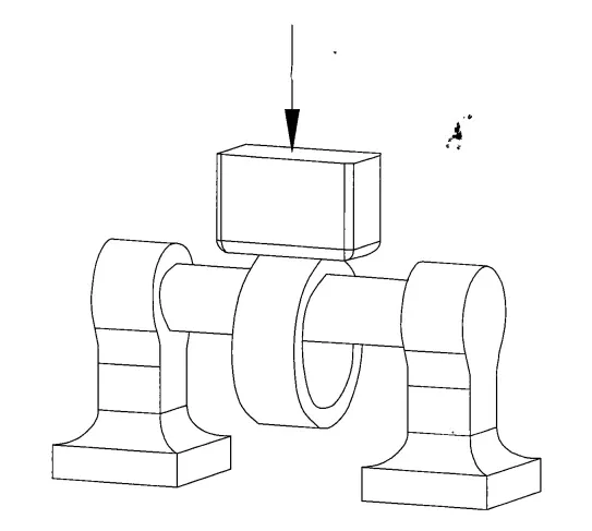
Figure 1 is a schematic diagram of the manufacturing process of pressure shells using the horse carrying technique;
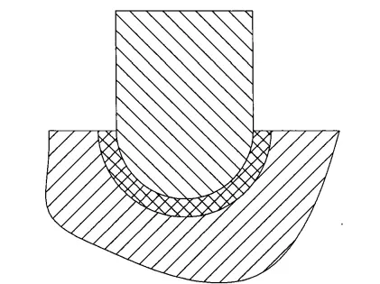
Figure 2 is a schematic diagram of the production of pressure shell heads using compression technology;
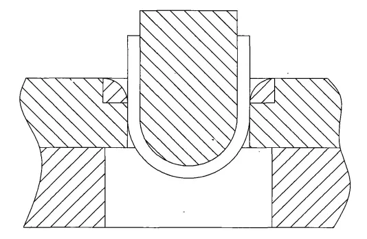
Figure 3 is a schematic diagram of the shell head formed by drawing thick sheet metal;
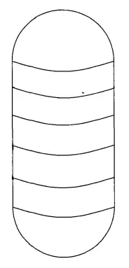
Figure 4 is a schematic diagram of a nuclear pressure shell processed by existing technology;
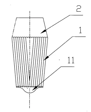
Figure 5 is a schematic diagram of the steel ingot in the first processing step of the present invention;
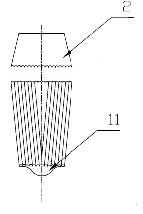
Figure 6 is a schematic diagram of cutting the riser in the second processing step of the present invention;
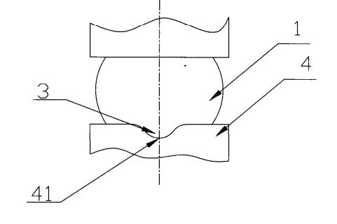
Figure 7 is a schematic diagram of the upsetting steel ingot in the third processing step of the present invention;
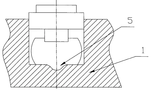
Figure 8 is a schematic diagram of the pressure center hole in the fourth processing step of the present invention;
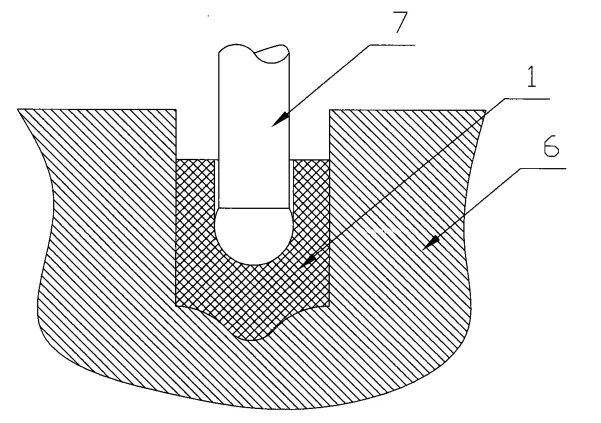
Figure 9 is a schematic diagram of hot perforation in the fifth processing step of the present invention;
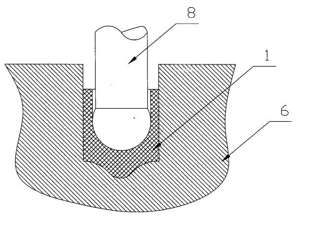
Figure 10 is a schematic diagram of the hot perforation and hole enlargement process after the fifth processing step of the present invention;
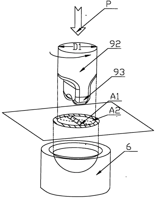
Figure 11 is a schematic diagram of the distribution extrusion process in the sixth processing step of the present invention;
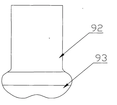
Figure 12 is a front view of the extrusion shaft in the distribution extrusion process of the present invention;
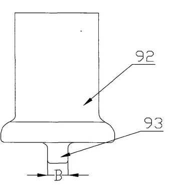
Figure 13 is a left side view of the extrusion shaft in the distribution extrusion process of the present invention;
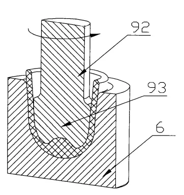
Figure 14 is a sectional view of the distribution extrusion process in the sixth processing step of the present invention;
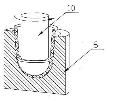
Figure 15 is a schematic diagram of the finishing process in the seventh processing step of the present invention.
Specific implementation method
Example: A distributed extrusion process method, the steps of which are as follows:
a. Refined steel ingot 1: heated to a high temperature between 1050 and 1250 degrees Celsius;
b. Cutting off the steel ingot riser 2: Various flame cutting methods such as oxygen acetylene can be used. Considering that the current level of steelmaking sometimes requires cutting off both the steel ingot riser and the bottom of the steel ingot, whether it is necessary to cut off the bottom of the steel ingot depends on the actual refining quality of the steel ingot bottom;
c. Upsizing the steel ingot and forming a steel ingot bottom centering structure 3: Place the steel ingot on the upsetting mold 4, and place the arc-shaped protrusion 11 below the steel ingot in the centering groove 41 of the upsetting mold. Then apply force above the steel ingot to upsetting it, so that the steel ingot is upsetting while the arc-shaped protrusion 11 below it forms a regular steel ingot bottom centering structure 3. The upsetting steel ingot can be upsetting in an open or closed mold;
d. Pressure center hole: Positioned by the steel ingot bottom centering structure 3, the upper plane of the steel ingot is punched by a center punch 5 with a guiding device, forming a center hole with a set depth and diameter on the upper plane of the steel ingot;
e. Hot perforation: Place the steel ingot in a fixed position into the prestressed extrusion cylinder 6 (with the steel ingot bottom centering structure facing downwards), align the center of the first perforation needle 7 with the center hole on the upper plane of the steel ingot, and extrude the steel ingot downwards. Deepen the depth and increase the diameter of the center hole on the upper surface of the steel ingot to the set value;
f. Distributed extrusion steel ingot: Place the steel ingot in a fixed position into the prestressed extrusion cylinder 6 (with the steel ingot bottom centering structure facing downwards, positioned according to the steel ingot bottom centering structure). The extrusion head 93 of the extrusion shaft 92 squeezes the metal downwards along the center hole of the steel ingot with an extrusion force P of 100000-150000 tons, causing the metal to flow radially to form the bottom of the shell and rise along the shell busbar to form the straight cylindrical part of the shell. Then, the extrusion shaft drives the extrusion head to move upward and reset (return). The extrusion shaft 92 rotates radially with the extrusion head 93 by a set angle α, and the extrusion shaft 92 repeatedly squeezes the metal downwards along the center hole of the steel ingot 1 with the extrusion head 93. Each set angle α rotated by the extrusion shaft 92 with the extrusion head 93 is one. The distributed extrusion process is repeated until the upper end surface of the extruded billet formed by steel ingot 1 tends to be flat, This process is to place steel ingot 1 in a closed prestressed extrusion cylinder 6, and repeatedly extrude steel ingot 1 in different regions and time domains through the extrusion head 93 of the extrusion shaft 92. The metal flows approximately radially away from the extrusion head 93 after being squeezed by the extrusion head 93. According to the minimum resistance law of metal flow proposed by the former Soviet scholar Gubkin, the metal flows the fastest at the position with the largest distance between the extrusion head 93 and the inner wall of the center hole of steel ingot 1. Therefore, when the extrusion head 93 squeezes the center hole of steel ingot 1, the flowing metal enters the gap between the prestressed extrusion cylinder 6 and the extrusion shaft 92, and then turns upward along the generatrix of the shell, making the height of the straight tube of the steel ingot shell higher than that of the part where the metal flows faster. In other parts, as the extrusion head 93 rotates continuously in the same direction to squeeze the center hole of the steel ingot, And after each distributed extrusion steel ingot step, the extrusion head rotates by a set angle α, so that the upper end of the extruded billet formed by steel ingot 1 eventually tends to be flat. Obviously, the smaller the radial rotation set angle α of extrusion head 93, the smaller the height difference of the upper end of the extruded billet formed by the steel ingot. Several distributed extrusion steps form a distributed extrusion process, that is, one distributed extrusion process contains several distributed extrusion steps: the number of distributed extrusion steps=360/set angle α;
g. Finishing: The finishing extrusion shaft 10 presses the surface of the inner cavity of the extruded billet formed by the steel ingot along the center of the steel ingot, flattens the surface of the inner cavity of the extruded billet formed by the steel ingot, and evenly squeezes the wall thickness of the steel ingot shell. The finishing extrusion shaft 10 in the finishing process can rotate appropriately after rising, and then press again to eliminate the influence of eccentricity of the finishing extrusion shaft 10 and improve the finishing accuracy;
h. The f-th distribution extrusion steel ingot process alternates with the g-th finishing process until the height, thickness, and end face flatness of the extruded steel ingot reach the set values.
The speed at which the extrusion head 93 of the extrusion shaft 92 presses the steel ingot downwards along the central hole of the steel ingot during the distribution extrusion of the steel ingot is related to the material of the steel ingot, specifically:
The steel ingot is made of black metal (such as high-temperature metal, steel containing steel, etc.), and the extrusion head 93 has a downward extrusion speed of 5mm/s-90mm/s;
The steel ingot is made of non-ferrous metals (such as aluminum, copper, etc.) and the extrusion head 93 has a downward extrusion speed of 20mm/s-300mm/s.
The upward (return) and downward (empty path downward) velocities of the extrusion head 93 when not in contact with metal are both 90mm/s-300mm/s.
When extruding steel ingots, the extrusion shaft 92 rotates radially with the extrusion head 93 at a set angle α of 10 degrees to 120 degrees.
The compression amount of the distributed extruded steel ingot process is between 2-2000mm.
The pressing speed of the finishing process, as well as the upward (return) and downward (empty stroke downward) speeds of the finishing extrusion shaft when not in contact with the metal, are the same as the pressing speed of the distributed extrusion steel ingot process and the upward (return) and downward (empty stroke downward) speeds of the punching head when not in contact with the metal, but the pressing amount of the finishing process is 0.01 to 0.5 times that of the distributed extrusion process.
After the hot perforation process, there is a hot perforation and expansion process: a second perforation needle 8 with a radial diameter greater than the first perforation needle 7 is used to press the steel ingot along the center hole on the upper surface of the steel ingot to expand the deepened center hole of the steel ingot.
A distributed extrusion die for a distributed extrusion process method, comprising an extrusion shaft 92, an extrusion head 93, and a prestressed extrusion cylinder 6, with the direction of use as the reference. The upper end of the extrusion head 93 is fixed at the lower end of the extrusion shaft 92, and the cross-sectional area A1 of the extrusion head is smaller than the cross-sectional area A2 of the extrusion shaft, which can effectively reduce the extrusion force P and improve the forming efficiency. The ratio A1/A2 of the cross-sectional area A1 of the extrusion head to the cross-sectional area A2 of the extrusion shaft is a function of the extrusion force P. The commonly used cross-sectional area of the extrusion head 93 is a rectangular surface, with its long side equal to the diameter D1 of the extrusion shaft, and its short side, which is the ratio B/D1 of the width B of the extrusion head to the diameter D1 of the extrusion shaft, to the extrusion force P, forms a functional relationship with the extrusion force P. The force P forms a functional relationship, and the centers of the prestressed extrusion cylinder 6, extrusion shaft 92, and punching head 93 are collinear, The prestressed extrusion cylinder 6 is a barrel shaped cylindrical body with an inner diameter larger than the outer diameter of the extrusion shaft 92 and the extrusion head 93. When in use, the upper end of the extrusion shaft 92 can be disassembled and fixed on the lower pressing device of the forging press, and the lower end of the prestressed extrusion cylinder 6 can be disassembled and fixed on the worktable of the forging press. Due to the huge three-dimensional compressive stress caused by the extrusion shaft 92 and the extrusion head 93 in the closed cavity of the prestressed extrusion cylinder 6, the metal is extruded in zones and batches to form a semi spherical part of the bottom of the shell, and the metal rises along the busbar to form the straight cylindrical part of the shell. In this way, the extruded shell, that is, the head and the cylinder, are formed as a whole structure. Also, it is extruded under the action of three-dimensional compressive stress. The strength of the shell is guaranteed.
The extrusion shaft 92 and the punching head 93 of the distributed extrusion mold are an integral structure.
The ratio A1/A2 of the cross-sectional area A1 of the extrusion head of the distributed extrusion die to the cross-sectional area A2 of the extrusion shaft is between 0.1 and 0.9.
The inner cavity of the prestressed extrusion cylinder 6 of the distributed extrusion mold is one of circular cavity, rectangular cavity, and elliptical cavity, and the cross-section of the extrusion shaft 92 is one of polygonal and elliptical.
The cross-section of the extrusion head 93 of the distributed extrusion die is a rectangular structure, with the long side equal to the diameter D1 of the extrusion shaft and the short side being the width B of the extrusion head. The ratio of the width of the extrusion head to the long side B/D1 is 0.05-0.95.
2024 November 5th Week WBM Product Recommendation:
Interroll Tapered Roller:
Interroll Tapered Roller is a major products of Henan Weichuang Bearing Precision Technology Co.,Ltd.(WBM). If you need more details, please click the website to know more.
https://www.bearingroller.com/rolling-elements/interroll-2tapered-roller.html