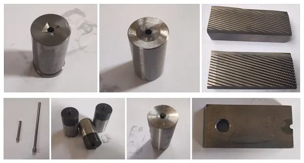
Abstract: The efficiency of batch processing of small cutter plates is relatively low. A fixture is designed to improve the processing efficiency and accuracy of small cutter plates.
Keywords: targeted sales; Leverage principle; degree of freedom
1. Preface
The small cutter plate refers to a cutting cutter plate specifically designed for automatic bearing riveting machines, and the cutting edge is processed using a CNC wire cutting machine. Due to the fact that the machining process of CNC machine tools is a single machine operation, the efficiency is relatively low during batch processing. So how to improve the processing efficiency and accuracy of small cutter plates is a new problem that arises in the actual processing process.
2. Overview of Small Cutter Plate Structure
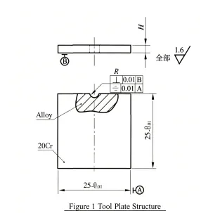
The important cutting component of the fully automatic riveting machine Z is the small blade plate. Due to the high-speed cutting of rivet threads by the blade, it is necessary to ensure that the geometric circle of the rivet cutting area remains unchanged, without leaving any scratches or cuts. The small cutter board has a simple structure, long service life, and stable cutting quality. The blade structure is shown in Figure 1, with a regular semi-circular blade. The circular blade ensures left-right symmetry on the blade and must maintain positional accuracy in the symmetrical axial direction. The consumption of small cutter blades is high. The cutting edge is made of hard alloy, while the cutting plate is made of un quenched 20Cr steel, suitable for digital control high-speed wire cutting machine processing.
3. Requirements for tooling position and precision position
(1) Ensure that the axis of the small cutter blade is perpendicular to the reference plane (large plane) by 0.01mm.
(2) The circular blade ensures left-right symmetry on the blade plate, with a symmetry value of 0.01mm.
(3) Ensure the positional accuracy of the blade axis of the small cutter plate on the blade plate.
4. Fixture design
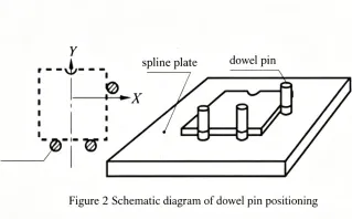
The tire hole plate used in the tooling must ensure that the parallel difference between the two ends of the processed plane is within 0.02mm, and the perpendicularity of the molybdenum wire should be less than 0.3% to ensure the perpendicularity of the small blade axis and the reference plane (large plane). According to the processing drawing, positioning pins are used for positioning, with two positioning pins on the bottom of the small cutter plate and one positioning pin on the right side. Combined with the plane positioning of the tire hole plate, this limits the degrees of freedom of the small cutter plate in the X, Y, and Z directions, as shown in Figure 2. After Z, when machining the positioning pin hole, (0,0) is used as the program origin for machining, and at the same time, the machining process is small
The origin of the main program of the cutting plate also coincides with (0,0), which ensures the accuracy of the positioning pin hole position and the positioning accuracy of the cutting plate. As for the symmetry of the small blade and the positional accuracy of the cutting edge, it depends on the accuracy of the machine tool itself to ensure.
Due to the need to ensure that the small cutter plate is completely pressed against the positioning pin during processing, the small cutter plate needs to be clamped in both X and Y directions, relying on the lever principle for clamping to ensure the clamping position. The designed tooling is shown in Figure 3.
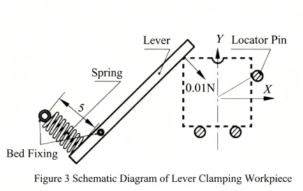
The lever force is on the angle bisector of the coordinate system XOY, ensuring clamping force in the X and Y directions.
Selection and fit tolerance of pins: Steel pins with good rigidity and roundness are selected for quenching and grinding. The fit between pins and holes is a relatively small interference fit. Taking a standard cylindrical pin with a diameter of Φ 4mm as an example, the tolerance of the pin is that the interference amount Z after cutting the hole is 0.01mm. It should be noted that when cutting the tire hole plate, the interference amount should not be too large to prevent vibration of the tire hole plate when inserting the pin, which may cause the reference to be lost.
The clamping force of the lever is applied at the corner of the small cutter plate, so that the force is evenly distributed along the 135 ° direction. The force needs to make the small cutter plate accurately rest on the positioning pin. The long end of the lever is located on the side of the small cutter plate. After setting, the force in both X and Y directions is about 0.007N, and the ratio of the length of the lever is 4:1. The force at the long end is 0.01N, and the force at the short end is 0.04N. After selecting a spring with an elastic coefficient of 4, only 1cm of travel is needed to achieve the selected force. The distance between the small end and the spring pin is 5cm, and the spring length is selected as 4cm.
5. Conclusion
After the assembly of the tooling is completed, the small cutter plate is clamped and processed with a wire cutting machine, and the first piece is successfully produced.
After passing the first piece trial cutting inspection, a large batch of small cutter plate processing was carried out, and after inspection, it was proven that this method is completely feasible.
2026 May 2nd Week WBM Product Recommendation
Rolling Dies:
As one of the professional tool manufacturer, provides rolling die with high hardness,fast delivery and good service.
https://www.bearingroller.com/tools/rolling-dies.html