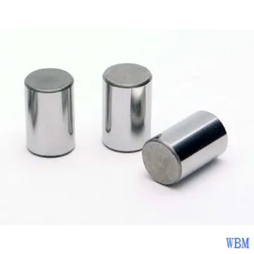
Abstract: The finished taper roller with a half angle of 3 ° is a large taper angle circular dimensional roller. When using a horizontal cold machine to process this type of tapered roller, it is very difficult to contain material in the inner cavity of the mold, resulting in material loss. The reason for this phenomenon is deeply explored, a solution is proposed, and a calculation formula is provided.
Keywords: large cone angle tapered roller: working sleeve, bottom mold
1. Introduction
There are usually two feeding methods for rollers, one is formed by turning with a lathe, and the other is formed by cold stamping with an automatic cold heading machine. Generally, cold heading forming is preferred because it is fully automated, capable of processing 106 rollers per minute, with high production efficiency and very low labor intensity for workers. The processing form of the automatic cold heading machine is to cut the strip into sections at station 1 and send them to the punching model cavity at station 2. The punching head is used to strike the material section and form it. The size of the mold cavity is designed based on the corresponding roller size. When the cone angle of the roller is large, the angle of the mold cavity is also large (to reduce the grinding amount in the subsequent process). Due to the horizontal position of the material section in the punching mold, when the mold cavity angle is large, the material section cannot be contained, resulting in material falling. In conventional design, the concave mold cavity adopts a "one" angle. For large cone angle rollers, if a conventional design is used, the material cannot be retained, resulting in material loss. Therefore, it is proposed to design the mold control into two "angles. The upper angle of the mold cavity is close to the angle of the finished roller, and the bottom of the mold cavity adopts a small angle, resulting in an increase in the small end diameter allowance. To determine the appropriate size of the small end allowance, it is necessary to assume that the diameter allowance is calculated at the parting point, When the outside allowance of the mold is close to the conventional diameter allowance (at which point the grinding allowance is the minimum), the allowance is calculated based on the assumption that the allowance is small.
2. Mold design drawing
The punching mold adopts a combination structure, with assembly diagram shown in Figure 1, working sleeve shown in Figure 2, and bottom mold shown in Figure 3.
The symbols are explained as follows:
rp1- Axis chamfer coordinate of mold bottom
Dp - Raw material diameter
LA work sleeve height
h - Maximum height of the material section from the bottom
H - Parting position
Dc - Finished roller diameter at the parting point
Dd - Conventional Process Allowance
Dm - diameter of the mold cavity opening
DA - Maximum diameter of the working sleeve
rp2- Radial chamfer coordinates of the mold base
β- Mold cavity draft angle
D1- Small end diameter of finished roller
h1- Minimum height of the material section from the bottom
Dy - Mold cavity diameter at the parting point
Dyc - Allowance at parting
 - finished roller half angle
L - Bottom mold height
dml - diameter of the lower part of the taper hole
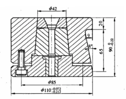
Figure 1 Die Assembly Diagram
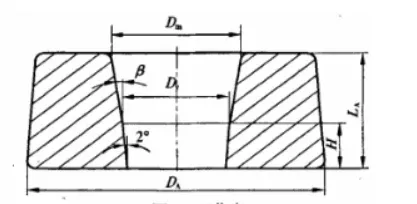
Figure 2 Workset
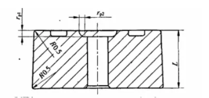
Figure 3 Bottom mold
3. Design formula
3.1 Calculate the punch position according to the conventional allowance and design method, with the chamfer coordinate rp1 constant for the bottom of the mold, the radial chamfer coordinate rp2 constant for the bottom of the mold, the height of the work sleeve LA constant, the diameter of the raw material Dp constant, and the draft angle of the mold cavity β Constant size.
3.2 The lower draft angle of the concave mold cavity is taken as 2 °.
3.3 Dr=Dp constant+0.1mm
3.4 Estimate the diameter allowance dd1, calculate the corresponding results according to conventional design standards, and calculate
h=[(Dp -dml)/2] * tg2 °, determine H=h+1
3.5 Calculate h1=[(Dp-dml+material diameter deviation - mold cavity size deviation)/2] * tg2 °, h1 must be greater than rp1.
3.6 Calculate the mold allowance:
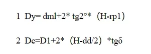
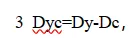
When the margin at the parting is close to the process margin dd, the experimental data dd1 and its calculation results are adopted
3.7 The dimensions of the punch are completely calculated using conventional methods.
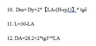
3.8 β=β Constant+10 '
3.9 LA=LA constant+rp1 constant - rp1
4. Conclusion
Prior to the design of this method, large taper angle tapered rollers cannot be machined using a horizontal cold heading machine. The above design methods have been applied in practical production and the results are very ideal. It not only reduces the labor intensity of workers but also improves production efficiency, saving considerable funds.
2023 New Week WBM Product Recommendation:
Interroll Tapered Roller:
Interroll Tapered Roller is a major products of Henan Weichuang Bearing Precision Technology Co.,Ltd.(WBM). If you need more details, please click the website to know more.
https://www.bearingroller.com/rolling-elements/interroll-2tapered-roller.html