Taking GB5786-M8 hexagonal head bolt as an example to illustrate Cold heading forging process is a metal pressure machining process with little or no cutting. It is a processing method that utilizes the plastic deformation of metal under external forces, and with the help of molds, redistributes and transfers the volume of metal to form the required parts or blanks.
I. The characteristics of cold forging process:
Cold heading is carried out under normal temperature conditions. Cold forging can improve the mechanical properties of metal parts.
Cold heading forging process can increase material yield. It is a pressure machining method based on plastic deformation, which can achieve less cutting or no cutting. The general material utilization rate is above 85%, with a maximum of over 99%.
It can improve production efficiency. The deformation time and process of metal products are relatively short, especially when processing parts on multi station forming machines, which can greatly improve productivity.
Cold forging process can improve the surface roughness of products and ensure product accuracy.
II. Requirements for raw materials in cold heading forging process
1. The chemical composition and mechanical properties of raw materials should comply with relevant standards.
The raw materials must undergo spheroidization annealing treatment, and their metallographic structure is spherical pearlite with grades 4-6.
The hardness of raw materials, in order to minimize the tendency of material cracking and improve the service life of molds, it is also required that cold drawn materials have the lowest possible hardness to improve plasticity. The hardness of raw materials is generally required to be between HB110~170 (HRB62-88).
The precision of cold drawn materials should generally be determined based on the specific requirements and process conditions of the product. Generally speaking, the precision requirements for reduced diameter and strong shrinkage dimensions are lower.
The surface quality of cold drawn materials requires a lubricating film with a dull dark color, and the surface must not have defects such as scratches, folds, cracks, burrs, rust, oxide skin, pits, and pits.
It is required that the total thickness of the decarburization layer in the radius direction of the cold drawn material should not exceed 1-1.5% of the diameter of the raw material (the specific situation depends on the requirements of each manufacturer).
To ensure the cutting quality during cold forming, it is required that the cold drawn material has a hard surface and a soft core.
Cold drawn materials should undergo cold forging tests, and the lower the sensitivity of the material to cold work hardening, the better, in order to reduce the increase in deformation resistance caused by cold work hardening during the deformation process.
III. Brief description of fastener processing technology
Fasteners are mainly divided into two types: one is threaded fasteners; Another type is non threaded fasteners or connectors. Here is a brief description only for threaded fasteners.
The processing flow of threaded fasteners generally consists of cutting, cold heading, or cold extrusion, cutting, thread processing, heat treatment, surface treatment and other production processes.
The general process flow for material modification is:
Pickling → Wire drawing → Annealing → Phosphating and saponification → Wire drawing → (Spheroidizing and phosphating)
The cold joining process for threaded fasteners requires the following situations:
Processing process for threaded fasteners below grade 8.8
Starting → Cleaning → Thread Rubbing → Cleaning → Surface Treatment → Packaging
Processing process for threaded fasteners below grade 8.8
Starting → cleaning → cutting → heat treatment → threading and threading → cleaning → surface treatment → packaging
Process flow of 8.8-10.9 level threaded fasteners
Starting → Cleaning → Cutting → Thread Rubbing → Heat Treatment → Cleaning → Surface Treatment → Packaging
Process flow of threaded fasteners for grades 10.9-12.9
Starting → Cleaning → Heat Treatment → Cutting → Thread Rolling → Cleaning → Non destructive Testing → Cleaning → Surface Treatment → Packaging
IV. The Basic Method of Cold Heading Forging Process Design
The design of cold forging process is actually the design of cold forging molds, and every process plan we design ultimately needs to be achieved through mold design.
Cold heading forging process design:
Firstly, calculate the length of the blank based on the specific relevant parameters of the product. At this time, the calculated weight is actually the net weight of the part. The length of the blank during cold forging can be determined based on the principle of constant volume, that is, the volume of the plastic deformation blank is equal to the volume of the part after plastic deformation. If cutting processing is still required, the volume of the billet should also be added with the corresponding cutting amount. The weight calculated after adding the corresponding cutting allowance is actually the gross weight of the part.
Secondly, the determination of deformation degree and forging frequency.
As shown in the figure, when the aspect ratio is ≤ 2.5, forging is performed once:
When 2.5 ≤ aspect ratio ≤ 4.5, secondary forging:
When 4.5 ≤ aspect ratio ≤ 6.5, forge three times.
The above data can only be achieved under ideal conditions. In actual production, the geometric shape of the product should also be considered, and to ensure quality, an additional forging deformation is required according to the above data.
Thirdly, determine the processing technology plan. Based on the specific requirements of the product, determine whether to use non cutting machining technology or less cutting machining technology and which production equipment to use, and design a machining step diagram to determine the machining process plan.
Fourthly, determine the billet diameter size of all materials based on the above three factors. It should be noted that the size of raw materials is closely related to the size of the product head, the size of the product rod, production equipment, thread accuracy, and surface treatment method of fasteners.
Fifthly, calculate the net weight of the parts based on the relevant parameters of the product, and calculate the consumption quota of the parts according to different processing methods and methods.
Sixth, determine the diameter size of the rolled thread blank according to product requirements. Different thread standards require different diameters of the rolled thread blank. In the new national thread standard GB192-81-GB2516-M8, there are four main types of external threads: 6e, 6f, 6g, and 6h. Please refer to the TFS Threads document for the introduction of relevant thread information.
Seventh, cold heading and forging processing technology and mold design.
The following is a process diagram for cutting hexagonal bolts:
K=Head height
k. =Head twisting height
Cutting → Preforming → Final Upsetting → Cutting Hexagons → (Thread Rubbing)
Figure 3 Process Steps for Non Cutting Machining of Hexagonal Head Bolts:
Cutting → Preforming → Shaping → Upsetting Hexagonal → (Rubbing Thread)
1. Design of feeding roller
The external dimensions and aperture dimensions of the feeding wheel are determined by the cold forging equipment manufacturer and do not require redesign. We only need to design the working groove size of the feeding wheel, and the groove size depends on the maximum diameter of the raw material line, with a tolerance of H110-H11.
The diameter of the cutting edge is generally the maximum size of the raw material diameter, with a tolerance of H9-H10.
The diameter of the cutting die is generally the diameter of the raw material: the maximum size+(0.05-0.10), with a tolerance of H9-H10.
4. Design of Preformed Stamping Dies
The design principle of one punch is to require a maximum deformation ratio for the second forging process, and to avoid longitudinal bending of the metal fibers.
There are many methods for designing a punch mold, and currently there are mainly two typical methods.
One method is represented by the United States:
This method is based on the theory of plastic deformation nuclei, first determining the diameter Dk value of the large end of the cone, and then determining the size of the punching cavity.
According to the plastic deformation kernel theory, as shown in Figure 4, assuming that the diameter Dk of the large end of the cone is 1.4 times the diameter dm of the small end, the angle of the cone is α The angle is positioned at 12 °, and the insufficient metal volume is supplemented by adjusting the h part of the cylinder.
DM in the circle=diameter of the wire
This design method is not completely static, it varies with the hardness of the material. This method has a cone angle α For bolts only, for other head shapes, α The value varies.
Another method is represented by the Soviet Union.
This method is selected based on the aspect ratio α Corner, then determine other dimensions.
dm=wire diameter
5. Final forging die and main die design
The design of this punching die is relatively simple. Its design principle is based on the shape and size of the processed product head. If cutting is required, the corresponding cutting allowance should be considered.
D0=(1.04-1.1) emax, where emax is the maximum diagonal dimension of the hexagonal head bolt.
D=(0.9-0.95) S, where S is the size of the opposite side of the hexagonal head bolt
H=height of bolt head,
H=2H/3, where h is the depth of the mold cavity.
The main mold is mainly designed based on the processing technology requirements of each step of the parts, and here only the design method of the multi-layer prestressed main mold is described. Practice has proven that the multi-layer prestressed structure main mold is an effective method to solve radial cracking of the main mold, especially for prestressed composite main molds using hard alloy as the core.
The determination of the number of layers in a multi-layer prestressed structure is mainly based on the size of the unit pressure during cold forging, the size of the inner cavity, and the strength of the materials used.
There are two situations here:
In one case, the main mold core is allowed to work under tensile stress, which is made of high-strength mold steel. In this case, the internal pressure Pimax is determined:
When Pimax ≤ kg/mm2, it is the whole mode;
When 110kg/mm2 ≤ Pimax ≤ 160kg/mm2, a layer of prestressed sleeve is used;
When 160kg/mm2 ≤ Pimax ≤ 200kg/mm2, use two layers of prestressed sleeves;
The pressure inside the main mold is generally calculated based on the unit pressure of the punching die.
Another situation is that the main mold core is not allowed to work under tensile stress, and the main mold made of hard alloy (commonly known as tungsten steel) belongs to this type. In this case, the following Pimax values are selected:
When Pimax ≤ 110kg/mm2, a layer of prestressed sleeve is used;
When 110kg/mm2 ≤ Pimax ≤ 190kg/mm2, use a two-layer prestressed sleeve;
The ratio of the outer diameter of the prestressed sleeve to the inner diameter of the main mold is 4-6. As shown in Figure 7, if there is an intermediate prestressed sleeve, its relevant dimensions can be calculated based on relevant cold extrusion data.
6. Trimming Die Design
2024 March 1st Week WBM Product Recommendation:
Heading dies,Punch:
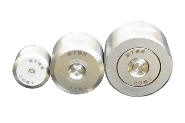
WBM produces taper roller dies with high efficiency and automation. Rollers are formed on a single automatic cold heading press and are fed, cut, and punched into the die for five steps.
We can produce different types and sizes taper roller dies with quality assurance,include:Combination Punch,Outside Sleeve,Blade,Combination Punch,Feed Cylinder,Combination Dies,Double Layer Sleeve,Insert.
https://www.w-bm.com/products/Taper-roller-cold-heading-dies/Heading-dies,Punch/400.html