Abstract
A forging press includes a set of molds, which have a fixed mold, a movable mold, and an external constraint. The movable mold has a reference plane, which is generally located on the plane of the workpiece perpendicular to the axis of the press, and three rotationally symmetrical sector blocks protruding above the reference plane. Each sector block includes a sector angle of a disk with a certain angle, which is separated from the other sector blocks by a certain angle. A pressing mechanism includes an axial drive mechanism for manipulating the movable mold to move in a direction parallel to the axis of the press, and an indexing mechanism for manipulating the movable mold to rotate around the axis of the press by a predetermined rotation angle.
Description
Closed die forging process and rotary step forging press
The present invention relates to a forging method for general axisymmetric products and a forging press, in which the general axisymmetric products are forged in a stepwise manner.
During the forging process, a machine called a forging press is used to press the workpiece in two or more forging dies. The shape formed by the plastic deformation of the workpiece is determined by the shape of the forging die and the magnitude of the pressing force. Forging may be completed in a single pressing stroke, or there may be multiple pressing strokes to gradually deform the workpiece into the required shape of the product.
The forging operation causes the workpiece to become thinner in the direction of force and causes it to stretch along a vertical plane, resulting in deformation to the final forged shape. The final forged shape of the workpiece is inevitably different from the final product shape. Because generally speaking, it is impossible or impractical to accurately forge the workpiece into the final required product shape. The degree of approximation between the final forged shape and the required product shape to some extent determines the difficulty of the forging operation. It is relatively simple to uniformly forge the entire planar view surface of the workpiece, which is called flat forging. However, in common cases involving complex shaped workpieces, flat forging leaves a large amount of material that needs to be cut to achieve the precise final required product shape. In a more advanced forging method, the workpiece is forged into a near net shape (NNS), which approximates the shape of the final workpiece but intentionally makes the size slightly larger for ultrasonic testing, removing enough material to accommodate deformation during heat treatment and final cutting allowance. In this NNS forging method, the amount of metal that needs to be cut off is relatively small. NNS forging requires more creativity in designing forging processes than flat forging.
Forging is widely used in various operations to produce small or large products. In order to deform the workpiece, the forging press must provide the required force. The production of large products is particularly complex, as the larger the product, the greater the forging pressure required. Therefore, larger and more expensive forging presses are needed to complete forging. As mentioned, NNS forging typically requires greater forging pressure than flat forging, and therefore requires larger forging presses.
In some cases, it is necessary to produce a product whose structural dimensions and materials are beyond the capacity of existing forging presses. To forge this product, it is well known that the open die forging operation can be used to perform step forging on the workpiece. In step forging, the design of the forging die and the operation of the forging press are as follows: at any given time, only a part of the workpiece is forged, and after each part of the forging, the workpiece moves relative to the forging die in steps, ultimately achieving complete forging of the entire workpiece. Unfortunately, open die forging and stepwise open die forging cannot achieve near final shape for most products, because the unconstrained parts on the workpiece can extend into any size and shape, rather than a near final shape.
In one application, the workpiece was forged into an axisymmetric turbine disc for use in large land-based gas turbines. The diameter of this turbine disc is 70-96 inches or larger. They are made of nickel based or iron-based high alloy steel and cannot be forged into the required near final shape even on a press with a capacity of 50000 tons. The mechanical properties required for the shape, size, and final turbine disk of the axisymmetric near final shape are quite strict. For this type of disc, the existing step forging technology cannot meet these requirements.
Therefore, an improved method is needed to forge large axisymmetric products. The present invention can meet this need and further provide corresponding features.
The present invention provides a stepper forging press and a technology for producing large axisymmetric near final shape forgings. The shape, size, and mechanical properties of forgings are suitable for precise operations, such as the final cutting of large land-based turbine disks. In the final forging operation, only a portion of the workpiece comes into contact with the forging die during each forging stroke, so the size of the workpiece may be larger than the forging capacity of existing forging presses. Compared to existing methods, the amount of final cutting required for the product has been significantly reduced. The latter is important because a major part of forging costs is the material consumption of the workpiece, which is a nickel based high alloy steel. Reducing the amount of material required for cutting also lowers the production cost of the product.
According to the present invention, the method of forging workpieces can be used for the operation of general original workpieces that are axisymmetric disc-shaped workpieces with a planar view surface. This method involves forging the entire planar view surface of the original workpiece first, and then step forging the first forged workpiece to make it the final forging shape. In the first forging operation, a forging die (non step type) that covers the entire planar view surface is used to forge the original workpiece. The radial inner part of the workpiece is preferentially forged to approximate the final forging contour, but the radial outer part of the workpiece is not forged to the final forging contour. In the subsequent step forging process, the radial outer part of the workpiece is first step forged into the final forging shape, without significant deformation of the radial inner part of the workpiece, although there may be relatively small radial inner deformation of the workpiece in the step forging process.
The present invention adopts closed die forging technology, which can forge products with larger radial and basically axisymmetric shapes compared to ordinary non step closed die forging technology. The maximum forging capacity of a forging press is determined by the maximum product size that can be forged by a closed die forging press. The use of step-by-step closed die forging enables larger (but otherwise identical) products to be forged using the same press and forging conditions. According to this aspect of the present invention, the method for forging large workpieces comprises the following steps: configuring a forging press with a maximum forging capacity sufficient to forge axisymmetric products with the largest final size using closed die forging. This method also includes providing axisymmetric workpieces and, under certain forging conditions, using closed die forging in a forging press to perform step forging on the workpieces, causing them to deform into step forging products. This product has a step forging final size that is larger than the largest non step forging final size. In order to make corresponding comparisons, all other forging conditions such as material, temperature, forging amount, and geometric similarity are the same, only the size of the workpiece and the mold have differences. 'Size' refers to the radial dimension measured outward from the axis of symmetry.
Step by step forging, preferably closed die step by step forging, is used to form a near final forging shape that approximates the required final product, but with slightly larger dimensions for ultrasonic testing, and to remove excess material to accommodate deformation during heat treatment and final cutting. The existing step type open die forging press and technology cannot produce near final shape in this application, so it is necessary to develop a closed die forging press and technology for forging axisymmetric, usually disc-shaped workpieces forged in the initial forging process.
According to this aspect of the present invention, a forging press comprises a fixed die having a fixed die surface and a movable die having movable die surfaces that are opposite to the fixed die surface along the axis of the press but are spaced apart from each other by a certain distance. The fixed mold surface can be flat, or it can be replicated based on the shape of the workpiece surface where the mold is placed. The movable die surface includes a reference surface located within the workpiece surface perpendicular to the axis of the press and at least one sector block, preferably three rotationally symmetric sector blocks protruding exactly from the reference surface. Each sector block includes a fan-shaped disk parallel to the axis of the press and having a fan-shaped angle relative to the axis of the press. There are more than one sector block, and each sector block is separated from other sectors by a certain angle. There is also an external annular extension constraint to prevent radial extension of the workpiece when it is compressed between the fixed mold and the movable mold. That is to say, forging is closed die forging rather than open die forging. The external constraint is preferably a circular outer wall, which can be separated or integrated with the fixed mold. The space enclosed by fixed molds, movable molds, and external constraints limits the volume of the workpiece that can be accommodated. The pressure mechanism includes an axial drive mechanism that can manipulate the movable mold to move in a direction parallel to the axis of the press; And the indexing drive mechanism can manipulate the movable mold to rotate around the axis of the press by a specified rotation angle. Although rotation and axial motion may coexist when the movable mold is retracted and no longer in contact with the workpiece, the axial movement of the movable mold and the rotational motion of the indexing drive mechanism can only be performed in the conversion mode when the movable mold comes into contact with the workpiece.
In general, a forging press consists of a set of molds, which includes a fixed mold and a movable mold that is opposite to the fixed mold along the axis of the press, but at a certain distance from each other. There is also an external constraint that extends in a circular shape around the volume of the workpiece. The space enclosed by the fixed mold, movable mold, and external constraints limits the volume of the workpiece it can accommodate. At least one of the fixed mold and the movable mold has a protruding shape on top. The pressing mechanism used is the same as described above.
In the preferred embodiment, there are three or more symmetrical fan-shaped protrusions above the reference plane area of the movable mold. Although there may be occasional local lateral and/or inward flow to fill the shape defined by the fan-shaped blocks, these fan-shaped blocks, in conjunction with external constraints forming closed die forging, cause partial deformation of the workpiece, resulting in the workpiece flowing generally radially outward. They also cause deformation in parts of the workpiece without sector blocks to induce metal flow.
The transition from each side of each sector block to the reference plane area on the side of the sector block should preferably have an oblique inclination of approximately 45 ° to 60 °. Without such an oblique angle, wrinkles or cracks may occur on the outer side of the workpiece that cannot be eliminated during subsequent forging strokes.
In the operation of a stepper forging press, the workpiece is loaded into the place where it is accommodated. The forging press forges a part of the workpiece during the first forging stroke in the axial direction. The force acting on the forging die is released, and at the same time, the mold retracts. The indexing drive mechanism operates the movable mold to rotate around the axis of the press by a specified rotation angle, and the axial drive mechanism provides another forging stroke. When forging the entire workpiece, this process will be repeated.
This forging press and forging method have made significant progress in the technology of forging large axisymmetric products. Forged products have a near final contour and are larger than products produced using existing closed die forging machines. The forged product is shaped into a near final contour, which reduces the overall material consumption and cutting requirements, thereby lowering the product cost.
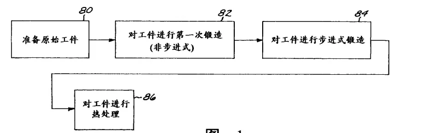
Figure 1 is a schematic diagram of the optimal forging process flow;

Figure 2 is a front view of the original workpiece;
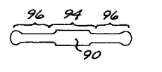
Figure 3 is a front view of the workpiece after the first non step forging process;
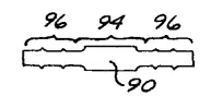
Figure 4 is a front view of the workpiece after step forging is completed;
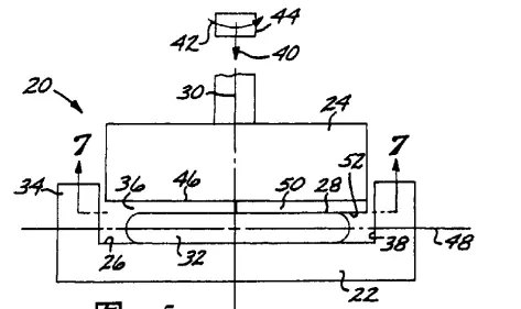
Figure 5 is a sectional view of the forging equipment of the present invention;
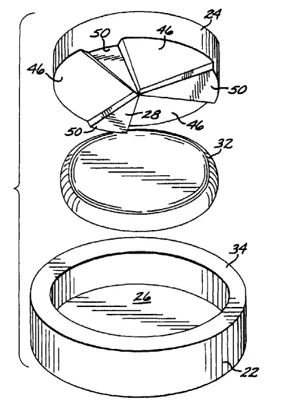
Figure 6 is an exploded perspective view of the forging without preparation shown in Figure 5;

Figure 7 is a top view of the movable mold taken along section 7-7 in Figure 5;
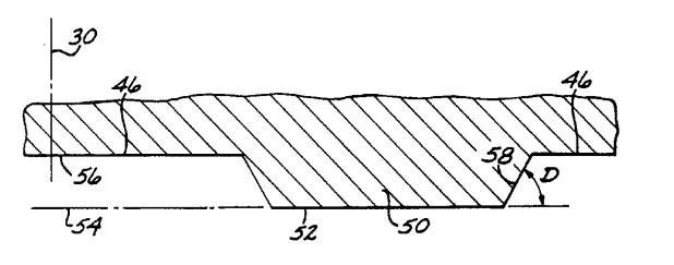
Figure 8 is a sectional view of the movable mold taken along line 8-8 in Figure 5;
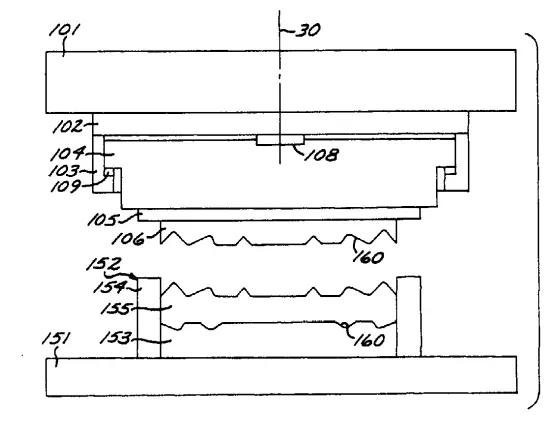
Figure 9 is a front view of a large forging press with movable die retraction;
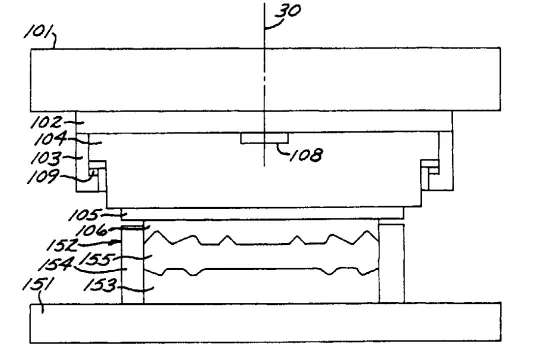
Figure 10 is a front view of the forging press shown in Figure 9 when the movable die contacts the workpiece;

Figure 11 is a sectional view of a turbine blade forged into a near final shape;
The best implementation scheme of the process of the present invention is shown in Figure 1. Number 80 is the original workpiece. The original workpiece can be made of any malleable metal, such as steel, aluminum alloy, iron-based high alloy steel, nickel based high alloy steel, or titanium alloy. The dimensions of the original workpiece are as follows: it contains enough metal to deform into the final forging shape where the metal flows towards it. The design of the original workpiece can use any known metal flow design technique. For the axisymmetric land-based turbine disk that the inventor is particularly concerned about, as shown in the figure, its final diameter is approximately 70-96 inches and thickness is about 20 inches. Its axisymmetric original workpiece 90 is a cylindrical body with a diameter of about 31 inches and a height of about 65-75 inches. The original workpiece 90 has an original plan view surface 92, which is the surface of the workpiece end that the forging die contacts during the first forging process.
Number 82, the original workpiece is first forged using a general non step forging process. In the first forging operation, when deformation is carried out, the forging die basically covers the entire planar view surface 92. The forging die can be a closed mold or an open mold, but it is best to use a closed mold. The shape of the forging die in the first forging is basically flat, although the cross-section may have a specified shape in the middle. As the metal mainly flows radially outward, the workpiece deforms towards the final required shape. In order to limit the shape of the forged workpiece, there are multiple sub processes and reheating of the workpiece within the scope of the first forging operation 82. It is best for the mold to deform the radial inner 94 of workpiece 90 into its final shape. The designated hub section as shown in Figure 3. However, do not attempt to forge the radial outer portion 96 of workpiece 90 into its final shape. If the first forging is an open mold, the radial outer portion 96 deforms into a shape that resembles a sphere, as shown in Figure 3. If it is a closed mold, it becomes a more fixed shape. It is often impossible to forge the radial outer portion 96 of the workpiece into its final shape because the forging ability of the forging press is not sufficient to cause the metal to deform into the required near final shape.
After the first forging of 82 is completed, the next step is to use closed die forging to forge the workpiece in a stepwise manner. The required step forging equipment and technology are not yet available. The following discussion is about a step forging press and technology researched by the inventor. In a stepper forging press, the forging die only contacts a portion of the planar view surface of the workpiece 90. Ideally, most of the forging force should be concentrated on the fan ring portion of the radial outer part 96 of the workpiece 90. Although there may be some forging on the radial inner portion 94, it experiences relatively little forging force and deformation. When the step forging process 84 is completed, as shown in Figure 4, the workpiece is deformed into a near final product, which has a radial outer portion mainly forged in process 82. This method is the best, but existing methods are also feasible under other conditions, such as step 82 for defining the final shape of the radial outer portion 96, or step 84 for defining the final shape of the radial inner portion 94.
Number 86 is an optional step for heat treatment of products with final shape, but it is preferable to have this step.
The existing process of combining non stepwise first forging and stepwise closed die forging has been developed for forging large and complex workpieces into near final shapes. This process is not intended to replace all general forging techniques, as it is more expensive to implement than general non step forging. However, due to limitations in the pressing capacity of forging presses or other reasons, the general forging process cannot achieve the final forged disc shape. Therefore, this method is practical and can obtain the near final shape structure of large forgings, achieving inevitable savings in materials, cutting processing, and other costs.
As pointed out, step forging equipment has been developed for the above-mentioned processes and other applications. Figure 5 shows a forging press 20 with a fixed die 22 and a movable die 24. The lower mold shows a fixed mold 22, while the upper mold shows a movable mold 24, although it can also be arranged in the opposite direction. Due to the workpiece being placed on the lower mold, the lower mold is a fixed mold 22. Fixed mold 22 has a fixed mold surface 26, and movable mold 24 has a movable mold surface 28. The fixed die surface 26 and the movable die surface 28 are opposite to each other along the axis 30 of the press, but are separated by a certain distance from each other. Molds 22 and 24 are usually preferably axisymmetric, although their surfaces may not be axisymmetric and may be replaced by non step like features. Workpiece 32 is placed between molds 22 and 24.
The radial outer constraint 34 in the form of an annular extension wall extends around the circumference of the workpiece. The molds 22 and 24 and the annular extension wall 34 define a closed mold workpiece accommodating position 36 that can fully accommodate the workpiece 34. The annular extension wall 34 can be a separate annular ring from the fixed mold 22 or integrated with the fixed mold 22. From Figure 5, it can be seen that before starting the forging operation, the workpiece may or may not contact the inward surface 38 of the annular extension wall 34. During the forging process, the workpiece 32 is compressed in a direction parallel to the axis of the press, and due to the radial outward flow of the metal, it undergoes radial expansion until it contacts the inward surface of the annular protruding wall 34, which limits further radial expansion of the workpiece 32.
This forging within a limited volume range is the essence of closed die forging and has become an important advantage over open die forging. In closed die forging, the metal undergoes plastic deformation radially outward, forcing it to transform into the shape defined by the mold and/or extension wall. On the other hand, in open die forging, the plastic deformation of the metal radially outward is not constrained, so that the metal undergoes plastic deformation radially outward along the path with the least resistance during forging without deforming into a defined shape. However, this is necessary for producing near final shape products. Therefore, closed die forging achieved results that were impossible to obtain with open die forging, including near final structures with surface shapes defined by the forging die.
Figure 6 shows partial sectional views of molds 22 and 24, annular extension wall 34, and workpiece 32.
The movable die 24 is movable in the direction parallel to the axis of the press and moves towards the fixed die during the forging stroke, as indicated by the axial arrow in Figure 5, and rotates around the press axis 30 in a specified manner, as indicated by the rotational arrow 42. (The movable die can also move in the opposite direction) When the movable die comes into contact with the workpiece 32, only one motion can be completed in the forging stroke direction and the rotation direction at a certain time. Therefore, these movements are optional, which will be discussed below. When the movable mold is retracted and no longer in contact with the workpiece 32, axial and rotational movements can be completed simultaneously. The movable mold 24 is moved by a pressing mechanism 44, which provides two types of movements 40, 42. The best way will be discussed below.
The fixed mold surface 26 is generally flat. It can also be replaced with an imitation shape. During the forging process, the flat or imitation shape of the fixed die surface is pressed onto the side of the facing workpiece (the bottom surface of the workpiece in the figure).
There are two types of shapes arranged in a circular pattern on the movable mold. These features can be seen in Figure 5-8. One of the features is that there is at least one fan-shaped reference surface area 46, preferably at least three, and only three is preferred. These fan-shaped reference surface areas 46 are essentially flat and usually parallel to the workpiece plane perpendicular to the press axis 30. Another feature is the presence of an equal number of sector blocks 50, whose upper surfaces are flat or contoured and parallel to the workpiece plane 48. As shown in Figure 8, the plane of the upper surface 52 of the sector block is set longitudinally along the axis 30 of the press, from the reference plane area 46 towards the fixed mold surface 26. In other words, sector block 50 protrudes above the reference plane area 46. The number of benchmark areas 46 is consistent with the number of sector blocks 50.
There must be at least one sector block 50, and if there are more than one sector block, it is best to set these sector blocks symmetrically with the same number of reference surface areas on the movable mold surface. That is to say, if there are two, three, four or more sector blocks, they should be arranged axially symmetrically when viewed from a plan view to minimize the asymmetric load of the forging press. If the number of sector blocks is less than three, it should be considered that the load on the sector blocks may be too high and the press may be subjected to asymmetric loads. For the super large capacity press used by the inventor, such as a 50000 ton press, it is important to consider load asymmetry in order to obtain the required shape and structure of the product, the service life and stability of the machine, and the safety of workers. For sectors 50 with three or more segments, the corresponding arc angles become relatively narrower. Therefore, they tend to bite into the metal more like circular bottomed steel caissons rather than deforming the metal through forging, resulting in ineffective plastic deformation of the workpiece. These theoretical and practical considerations lead to the adoption of three sector blocks 50 and three staggered reference plane regions 46 (as shown in Figure 7) as the optimal choice, although using fewer or more sector blocks 50 in the mold surface is feasible in some cases.
Fan shaped blocks 50 are symmetrically arranged at a certain distance around the movable mold surface 28, and each individual fan shaped block corresponds to a fan angle A. One of the reference plane regions 46 is arranged between each sector block 50, and is at an angle C relative to one of the reference plane regions. The sum of the angles A of all sector blocks, plus the sum of the angles C of the reference plane area used, is 360 degrees.
The angle A of the clamped sector block is preferably between approximately 45 ° and 65 °. If A is actually smaller, the mold may get stuck in the workpiece due to the action of the circular bottom steel caisson mentioned above. If it is actually larger, the mold will become more like a regular flat or shaped mold, and the effect of the torsional torque of the stamping ability of the step forging process will be very small. Angle C is determined by angle A and the number of sector blocks.
The geometric shapes of sector block 50 are shown in Figures 7 and 8. Fan block 50 is a pie shaped block, and when shown in Figure 7, it is a circular fan block. In the cross-sectional view of Figure 8, the sector block 50 includes an inclined sector block side surface 58 located between the upper surface of the sector block 50 and the reference plane 46. The sides 58 of these fan-shaped blocks can also be seen as quite narrow slices in the plan view of Figure 7. The side of the fan-shaped block is inclined at an angle D to the upper surface of the fan-shaped block. The optimal inclination angle D is approximately 45 ° to 60 °. If the inclination angle D is actually smaller than 45 °, the angle A of the sector block is actually enlarged, and the torsional torque effect of the stamping ability will be reduced. If the inclination angle D is actually greater than 60 °, the effect of biting or circular bottom steel caisson can be observed. In step forging, defects such as wrinkles and cracks will occur, which will be discussed below. Once these defects are generated, they cannot be completely eliminated in subsequent forging or other operations. The workpiece 32 is placed between the fixed mold 22 and the movable mold 24 for forging using a step forging process 84 or other processes. During the first forging stroke, operate the pressing mechanism to move the movable die surface 28 towards the fixed die surface 26. The workpiece deforms under the pressure state mentioned above. Reverse the pressing mechanism and retract the movable mold from the contact state with workpiece 32. Manipulate the pressing mechanism 44 to rotate the movable mold around the axis of the press by a predetermined value in an indexing motion. The selection of rotation value is related to the properties, shape, required limitations, and dimensions of the workpiece of the material. The rotation value of each transposition motion should be less than angle A. The thicker the material, the smaller the indexing rotation. As the optimal case, the rotation value for indexing is generally around 40 ° to 60 °. In a typical scenario, with three sectors and an angle A of 55 °, the optimal rotation value for indexing is around 40 °. After the rotational motion is completed, in the second forging stroke, operate the pressing mechanism 44 to move the movable die towards the fixed die surface 26. After the workpiece deforms, the pressing mechanism retracts the movable mold 24 from contact with the workpiece 32. Manipulate the pressing mechanism to rotate the movable mold 24. These processes are repeated multiple times to complete the forging. For the optimal situation: there are three sector blocks, angle A is 55 °, and the rotation value of the press is 40 °. The total sum of three forging strokes is required to complete one deformation. Multiple deformations can be used for thick forgings and forgings with high material strength. During the forging process, the workpiece is usually in a high temperature state and will cool down during the forging operation. In forging operations, the workpiece can be reheated whenever necessary to reduce its plastic strain stress and obtain specific microstructures in the workpiece.
The above discussion explains that the conventional form of stepper forging press is suitable for any top pressure loading device. The inventor's application is concerned with forging large impellers for gas turbines using nickel based high alloy steel or titanium alloy steel with a 50000 ton closed die vertical forging press. The huge size of the workpiece and the enormous forging load result in special considerations for the pressing mechanism of the mold.
Referring to Figures 9 and 10, the upper support plate 101 is a moving component of the forging press. The base surface 102 is fixed to the upper support plate by bolts, the ring 103 is fixed to the base surface 102 by bolts, and a rotating support plate 104 is rotatably fixed in the ring 103. The upper mold connection device 105 is fixed to the rotating support plate 104 by bolts. The upper mold 106, corresponding to the movable mold 24 mentioned above, is fixed to the upper mold connection device by bolts. The rotating support plate 104 is fixed in a centering fixture 108, which can rotate the rotating support plate 104 around the axis 30 of the press and allow the rotating support plate 104 to move up and down in the ring 103. The centering fixture 108 prevents the rotating support plate 104 from radially moving relative to the axis 30 of the press.
The lower support plate 151 supports the lower mold 152, corresponding to the fixed mold 22 mentioned above. The mold includes a lower mold 152 and an annular hole 154. The lower mold 152 and the annular hole 154 form an empty space in the lower mold, and the workpiece can be placed in the cavity of the lower mold.
In the retracted state, the opening position of the press in Figure 9, the rotating worktable is set on the support plate 109 fixed inside the ring 103. These support plates 109 allow the rotating worktable to easily rotate around the axis 30 of the press under the action of the hydraulic cylinder, thereby completing the rotational indexing motion. A stable, reliable, and relatively rapid rotational motion is observed, which improves the production capacity of forging presses and also enables rapid forging of hot workpieces when they are still hot enough. The above method enables rotation even in large forging press mechanisms.
As shown in Figure 10, during the contact between the upper mold 106 and the workpiece 155, the rotating support platform 104 is pushed upwards away from the support plate 109 and against the upper surface of the base surface 102. The frictional contact between the rotating worktable 104 and the base surface 102 restricts rotation. As shown in Figure 11, using imitation molds such as molds 106 and 153, the workpiece can be forged into a near final shape through closed die forging. The profile 160 of ordinary flat forging is generally equipped with corresponding flat molds for open forging, which are wrapped around the near final forging mold 162 and the final cutting workpiece. The near final forging mold is equipped with imitation molds 106 and 153. In each case, any excess material must be cut off to produce the final product. For both near final forging and flat forging, final cutting is inevitable. However, the final cutting process is much less for near final shape closed die forging than for flat forging. The shaded area represents excess material that must be cut from the flat open die forging beyond what is necessary to be cut from the near final shape forging. In this case, it is approximately 30% of the volume of the flat forging. When the workpiece is made of expensive nickel based high alloy steel, such as in the case of high-speed land-based gas turbines, the difference between the feed cost and the waste cost of excess nickel based high alloy steel materials may account for a relatively high proportion of the total product cost, such as 10-20% or more. Therefore, this technical method can achieve a variable cost savings in material costs and a fixed cost savings in forging workpieces at lower pressures than in other situations.
The production of products such as turbine blades using nickel based high alloy steel is generally carried out when the workpiece is at high temperatures. For example, to forge large blades for land-based turbines, the final blade diameter is 70-96 inches, weighing over 15000 pounds, made of nickel based high alloy steel such as Inconel706, and the workpiece needs to be heated in a heating furnace above its melting temperature, typically 1825 ° F. The recrystallized workpiece is transferred to the forging press, and then the workpiece is forged. The workpiece is cooled to the solidification temperature for a period of time, and then falls below the solidification temperature. When the workpiece cools down, the required forging pressure increases and its plastic deformation stress also increases, but the stepwise forging process allows forging to continue. The final step forging stroke is best performed at approximately 1750 ° F above the solidification temperature to achieve relatively small grain sizes of ASTM3-5. Metallographic studies have shown that the metallographic structure obtained using a stepper forging press and the process shown in Figure 1 is essentially the same as that obtained using general forging and heat treatment processes (although this method cannot successfully forge the very large workpieces of concern in this article). The above discussion specifically pertains to Incnel706, a preferred material used in the present invention. For other materials, other processes may be required, which falls within the scope of the present invention.
Although the present invention has been described in conjunction with specific embodiments, various improvements and enhancements can be made without departing from the spirit and scope of the invention. Therefore, the present invention is not limited to the claims.
2024 December 1st Week WBM Product Recommendation:
Rolling Dies:
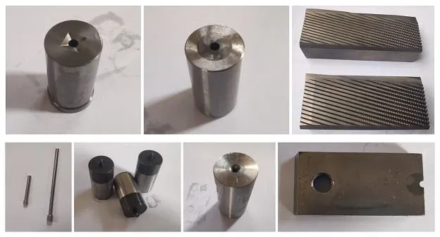
As one of the professional tool manufacturer, provides rolling die with high hardness,fast delivery and good service.
https://www.bearingroller.com/tools/rolling-dies.html