Abstract: Surface cracks on Railway Bearing rollers were analyzed using methods such as magnetic particle inspection, cold acid washing, and metallographic examination. The results showed that secondary quenching burns generated during the roller manufacturing process were the main cause of cracking on the rolling surface of the rollers. By taking measures such as reducing the grinding allowance of the roller end face, increasing the outer diameter grinding allowance, and strengthening the management of the sleeve, the burn caused by secondary quenching has been eliminated.
Keywords: Railway Bearings; Roller; Grinding; burn; crack
During the normal maintenance of the NJ (P) 3226X1 railway passenger car roller bearing after a maintenance period, magnetic particle inspection revealed one or several cracks roughly distributed along the axial direction on the rolling surface of individual rollers. The roller material is GCr15, and the longest installation and use time of the roller is 18 months. The maximum mileage of the bus has reached 700000 kilometers. The following text provides a detailed analysis of four cracked roller samples.
1. Inspection and analysis
1.1 Macroscopic morphology observation
Macroscopic observation and magnetic particle inspection were conducted on the crack morphology of rollers in 4 samples (numbered 1 # to 4 #), and no other forms of damage were found on their rolling surfaces and end faces except for cracks. The crack morphology of rollers 1 # to 4 # is shown in Figure 1, among which 10 cracks with a length of 4.7-9 mm were observed on roller 1 #; Four cracks with a length of 4-9.5 mm were observed on roller 2; A total of 11 cracks with lengths ranging from 3 to 20 mm were observed on roller 3; Two cracks with lengths of 40 and 45 mm were observed on roller 4.
1.2 Routine project inspection
The chemical composition, hardness, inclusions, and quenching and tempering structures of the four rollers were inspected in accordance with TB/T 3010-2001 "Technical Conditions for Ordering High Carbon Chromium Bearing Steel for Railway Rolling Bearings", JB/T 1255-2001 "Technical Conditions for Heat Treatment of High Carbon Chromium Bearing Steel Rolling Bearing Parts", and TB/T 2235-2010 "Quality Control Standards for Railway Rolling Bearings". The results showed that the raw materials and heat treatment quality of the rollers were within the qualified range and met the relevant standard requirements.
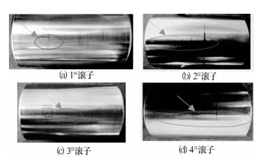
Figure 1 Crack morphology of roller
1.3 Acid washing inspection
Four cracked rollers were subjected to cold acid washing according to JB/T 1255-2001 standard, and it was observed that there were multiple light gray white or bright white marks along the circumferential direction on the rolling surface of the four rollers. The edges of the bright white areas were surrounded by dark black stripes, and the crack positions were all in the light gray white or bright white areas, which were typical burn morphology. The burn morphology of rollers 3 # and 4 # after acid washing is shown by the arrows in Figure 2 and Figure 3.
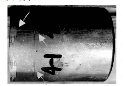
Figure 2-3 # Roller Cold Acid Wash Burn Morphology
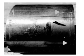
Figure 3 4 # Roller Cold Acid Wash Burn Morphology
1.4 Fracture analysis
Using a wire cutting device, the 4 # roller was cut horizontally. While protecting the original crack from damage, the other end of the crack on the 4 # roller was manually disconnected. The fracture morphology after opening is shown in Figure 4. Observing the fracture surface, it can be found that there are radial ridges on both sides of the elliptical box (corresponding to the gray white area of the surface marked by the elliptical box in Figure 3), as indicated by the arrow in the direction shown in the figure. Based on their direction, it can be determined that the burned area on the roller surface is the crack source area.
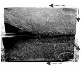
Figure 4: Fracture morphology of roller crack # 4
Metallographic examination on both sides of the 1.5 crack
Select the bright white area along the circumference of the 4 # roller, cut and grind it horizontally, and use 4% nitric acid alcohol to corrode it before placing it under a microscope for observation. It was found that there was no decarburization on both sides of the crack. The extremely thin white bright layer on the surface was a secondary quenched martensitic structure with a depth of about 10-30 μ m, and the high-temperature tempered structure below the surface was about 70-140 μ m. The core of the matrix was a normal metallographic structure. The crack starts from the white bright layer of secondary quenched martensite on the surface and extends to the matrix. The metallographic structure on both sides of the 4 # roller is shown in Figure 5.
From the above inspection results, it can be seen that one or several cracks appearing on the rolling surface of individual rollers in Railway Bearings are related to secondary quenching burns on the roller surface.

Figure 5: Metallographic Structure on Both Sides of Roller 4 #
2. Analysis of burn causes
2.1 Investigation and analysis of the use of cracked rollers
Railway Bearings are key components of the vehicle bogie, installed in pairs in the axle box and lubricated with railway IV grease. They must withstand certain radial and axial loads, and common faults include working surface peeling, fatigue cracks, pitting, and electric corrosion marks. Regarding the occurrence of roller cracks, on-site investigation found that except for a few rollers with burns and cracks, there were no abnormalities in the appearance, lubricant color, and lubrication status of other parts of the bearing. Magnetic particle inspection confirmed that no cracks were found on the inner and outer ring surfaces; According to the temperature data recorded by the vehicle axle temperature alarm, it can be seen that the temperature rise of the axle box bearing is also normal. Corrosion of the cracked roller rolling surface was carried out using a 3% nitric acid alcohol solution, and observation under a 400x microscope confirmed that there were no signs of electrical corrosion on the rolling surface. Due to the fact that the crack morphology of the faulty roller is a longitudinal straight crack of varying lengths, and the locations of occurrence are also on the rolling surface, the distribution pattern of the burn layer is different from that caused by electric erosion (the distribution pattern of the electric erosion layer is mostly circular arc). Therefore, it can be ruled out that the burn and cracking of the roller rolling surface are caused by poor lubrication or electric erosion during the operation of the bearing. Therefore, it can be concluded that the burn on the rolling surface of the roller occurred during the manufacturing process, and the cracking of the rolling surface of the roller may be due to the initiation and propagation of fatigue cracks at the burn site under alternating contact stress.
2.2 Formation mechanism and characteristics of grinding burns
When bearing parts are ground after heat treatment, high temperatures are generated on the surface of the parts due to the grinding heat, causing local changes in the surface structure and properties. This type of defect is usually referred to as grinding burn. Grinding burns are generally divided into two types: one is high-temperature tempering burns; The other type is secondary quenching burn.
The temperature range for high-temperature tempering burns is from above the tempering temperature of the part to below the critical temperature Ac1 of the steel phase transition, approximately between 200 and 745 ℃. At this temperature, the superficial martensite and residual austenite structures will decompose and transform into martensite or martensite structures, which have poor acid corrosion resistance and appear dark black after cold acid washing. Therefore, high-temperature tempering burns are also known as "black burns".
The local instantaneous high temperature generated by secondary quenching type burns occurs above the critical temperature Ac1 of steel transformation, which is about 800 ℃ or above. The superficial martensitic structure undergoes phase transformation and transforms into austenite, which is then cooled by cutting fluid and re quenched to form a secondary quenching martensitic layer. This structure is not easily corroded by acid, so after cold acid washing, the surface of the burn is gray white or bright white, and the surrounding area is dark black. Therefore, secondary quenching type burns are also known as "white burns". The secondary quenching type burn tissue will generate significant tensile stress on the surface of the workpiece, which can induce cracks under certain conditions. During the grinding process, the secondary quenching burn area is prone to generate grinding cracks under the action of grinding stress. Usually, the grinding cracks are very small and cannot be detected by naked eye observation. Magnetic particle inspection method must be used to identify them.
2.3 Investigation of Burn Injuries on Roller Processing Surface
The surface of roller grinding includes the outer diameter surface and two end faces. The outer diameter surface grinding process uses a through type centerless grinder for continuous grinding, which is divided into four processes: coarse grinding, fine grinding, fine grinding, and ultra precision. A total of 10 grinding and ultra precision processes are completed. The outer diameter surface of the roller is processed using a through type centerless grinder, with a small feed rate and good cooling conditions, and generally does not cause secondary quenching burns. The precision grinding outer diameter process adopts a fully automatic CNC centerless grinder, which has automatic diagnosis, alarm and protection functions. Once an abnormality occurs during the machining process, the equipment will issue a stop command, and it is also impossible to produce circular grinding burns. Investigation of the rough grinding outer diameter process, a total of 5009 inspection records of roller pickling were reviewed, and no grinding burn phenomenon was found. The roller end face processing adopts a horizontal double end face grinder to grind both end faces simultaneously, divided into coarse grinding and fine grinding processes. After investigation, it was found that there were traces of steel sleeve strain on the outer diameter surface of the rollers ground by the M775B1 horizontal axis double end grinder. After fine grinding of the outer diameter and acid washing inspection, it was found that there were burn marks on the outer diameter surface of the rollers.
2.4 Reproduction test
A simulation grinding test plan has been developed for the characteristics of centerless through grinding, which involves artificially increasing the grinding amount and speed, not timely dressing the grinding wheel, shutting down or reducing the cutting fluid flow rate, or sudden power outages during grinding. These test conditions cause the temperature in the grinding area to rapidly rise. After multiple tests, only scratches and spiral black burns on the outer diameter surface of the roller were found. However, simulation tests were conducted on the double end face grinder under harsh grinding conditions (using increased end face grinding, worn old sleeves, reduced cutting fluid flow, wheel passivation, etc.), and the results showed burn marks of a certain width on the outer diameter surface of the roller (Figure 6), indicating that grinding the double end face on the horizontal axis double end face grinder will cause secondary quenching burns on the outer diameter surface of the roller.
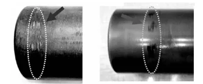
Figure 6 Burn marks generated by grinding double end faces
Through in-depth analysis of the grinding principle and characteristics of the double end face grinding process, it is found that when grinding rollers, the rollers enter the 25 cylindrical sleeves on the circular grinding disc of the grinder. The grinding disc rotates and sends the rollers into the grinding area of the grinding wheel. The grinding disc and the grinding wheel rotate relative to each other, and the left and right grinding wheels simultaneously grind the two end faces. During grinding, the outer diameter surface of the roller and the inner wall of the steel sleeve generate a large friction, forming an instantaneous high temperature. Due to the small gap between the sleeve and the roller, the cutting fluid is difficult to cool in time. When the grinding condition deteriorates (such as excessive machining allowance on the end face), the temperature will quickly rise above the critical temperature of the steel phase transition. When the roller rotates with the grinding disc to the reflux of the cutting fluid in the lower part, it will be rapidly cooled, resulting in secondary quenching type burns If the surface allowance of the outer diameter process is too small, The burn tissue was not removed and remained on the surface of the roller.
3. Preventive measures
When using a horizontal axis double end grinder to grind the roller end face, the outer diameter surface of the roller is prone to burns. The method to prevent burns is to reduce the frictional heat generation between the inner wall of the sleeve and the outer diameter surface of the roller. The recommended preventive measures include: (1) adjusting the process flow and increasing the grinding allowance of the outer diameter of the roller after grinding the double end face. Add the rough grinding outer diameter process and adjust the original rough grinding double end face process and fine grinding double end face process to after the rough grinding outer diameter process; Before the rough grinding of the outer diameter process, adjust the grinding allowance of the outer diameter after grinding the double end faces from the original 0.06-0.08 mm to 0.18-0.20 mm to remove the burn tissue layer on the outer diameter surface of the roller; (2) Reduce the grinding allowance of the double end faces of the roller. The clearance of the double end face has been adjusted from 0.45-0.60 mm to 0.20-0.40 mm, and a reasonable machining length dimension has been formulated. The dimensional change rate after heat treatment is strictly controlled to ensure that the length dimension of the roller entering the double end face grinding process is controlled within the standard tolerance range, reducing cutting force and friction on the inner wall of the sleeve; (3) Improve the sleeve structure. Make a cutting fluid pouring port on the outer surface of the sleeve, which can allow the cutting fluid to flow smoothly into the inner wall of the sleeve during processing, reduce frictional heat, and avoid surface burns; (4) Strengthen the management of important fixtures such as sleeves and strictly implement the regulations for replacing sleeves. When the number of rollers processed in the double end face grinding process reaches 200000 to 250000 or the roller end face runout exceeds the tolerance, all sleeves must be replaced; If there are still burn marks on the outer diameter surface of the roller after double end grinding and acid washing inspection (until the rough grinding outer diameter process), all sleeves should be replaced; (5) Improve process documents and standardize acid washing inspection standards. Specify the timing, frequency, and quantity of acid washing inspections, clarify the requirements for handling burn cases discovered during acid washing, and promptly and accurately identify burn quality issues.
2025 May 3rd Week WBM Product Recommendation:
Cutter:
WBM produces taper roller dies with high efficiency and automation. Rollers are formed on a single automatic cold heading press and are fed, cut, and punched into the die for five steps.
We can produce different types and sizes taper roller dies with quality assurance,include:Combination Punch,Outside Sleeve,Blade,Combination Punch,Feed Cylinder,Combination Dies,Double Layer Sleeve,Insert.