Abstract
It involves a progressive stamping die used for producing metal parts. There are upper and lower mold seats, upper and lower guide sleeves, upper and lower cushion plates, concave templates, retaining rings, inner guide columns, discharge plates, height limit plates, discharge springs, fixed plates, discharge screws, guide nails, and convex molds. The convex molds are equipped with rib cutting convex molds and pre cutting convex molds. The punching process of parts is divided into rib cutting, pre cutting, and precision cutting. The cutting groove is punched out on the strip by the cutting convex mold, and then the cutting groove is cut off by the pre cutting convex mold to roughly cut out the end face of the part. At the corresponding position, the precision cutting convex die is used to remove the precision cutting allowance and accurately cut out the shape of the part. Due to the sharpness of the rib cutting convex mold and the shallow depth of the rib cutting, not only does it cut off the surface of the material, but it also has much less traction on the material surface than normal punching. Due to the compression of the material during forming, the collapse angle generated is very small and not easily cracked. The pre cutting process will not increase the collapse angle on the surface of the parts. In the precision cutting process, the rough sections of the cut ribs and pre cut are removed to achieve the size of the part.
Description
A progressive stamping die
TECHNICAL FIELD
This utility model relates to a stamping die, particularly an improved progressive stamping die for producing metal parts.
Background technology
A progressive stamping die refers to a die equipped with an elastic discharge plate and precise positioning with guide pins for feeding, as shown in Figure 1. Existing progressive stamping dies generally have a lower die seat 1, a lower guide sleeve 2, a lower cushion plate 3, a concave template 4, a retaining ring 5, an inner guide column 6, a discharge plate 7, a height limit plate 8, a discharge spring 9, an upper guide sleeve 10, a fixed plate 11, an upper cushion plate 12, a discharge screw 13, an upper die seat 14, guide pins 15, and a convex die 16. Usually, parts produced by stamping naturally produce rounded corners, including fillet 21, bright band 22, fracture band 23, and burrs 24, on their cross-section (see Figure 2). The occurrence of corner collapse is due to the fact that punching relies on shear force to cut the material. During the shearing process, the material will undergo plastic deformation before fracture, that is, the surface of the part material will be pulled down by the punch, forming a corner collapse. The existence of the transition collapse angle between the surface of the part and the section at the junction of the arc reduces the effective area of the section; For products with this section as the working part or the joint between the upper surface and the section as the working part, it will have a significant adverse effect; Such as reducing lifespan and operating insensitivity. The existing methods to reduce the collapse angle include reducing the punching gap and making the convex die blade sharp. Although this method can reduce some collapse angles, the effect is not ideal. At the same time, due to the small gap, the convex mold wears out quickly, and the convex mold requires a sharp blade, so it is often necessary to repair the mold and sharpen the blade.
Summary of the invention
The purpose of this utility model is to provide a progressive stamping die that can significantly reduce the collapse angle of the punching section and ensure mass production of parts, reducing the maintenance and repair of progressive dies.
This utility model has been improved on the basis of the existing stamping die, and is further equipped with a rib cutting convex die and a pre cutting convex die. The cutting angle of the rib punch can be selected from 20 ° to 60 °, and the cutting depth is (0.2~0.5) t, where t is the thickness of the stamping material.
Due to the presence of a rib cutting punch and a pre cutting punch in this utility model, the stamping deformation mechanism of the parts has been significantly improved; Divide the punching process into three steps, namely: cutting ribs+pre cutting+precision cutting. At a certain step in the progressive stamping die, a rib cutting convex die is set, and a corresponding rib cutting groove is punched out on the material; In this mold, at a corresponding position in a subsequent step, the pre cut convex mold cuts off the rib groove and roughly cuts out the end face of the part. The position is at a certain distance from the part position, and this distance is the precision cutting allowance. At a subsequent step, the precision cutting allowance is removed by precision cutting convex die cutting at the corresponding position, and the shape of the part is precisely cut.
Using this method, due to the sharpness of the rib cutting punch and the shallow depth of the rib cutting, not only is the material surface cut, but the pull of the punch on the material surface is much smaller than normal punching. Meanwhile, due to the compression of the material during forming, the resulting collapse angle is very small. The cutting rib convex mold is made of materials with good toughness, and the cutting rib depth is shallow, so it is not easy to crack. In the pre cutting process, the cut material is cut off without affecting the surface of the part, that is, without increasing the collapse angle. In the precision cutting process, the rough sections of the cut ribs and pre cut are removed to achieve the size of the part. Due to the very small amount of precision cutting, the collapse angle is basically not increased.
After practical production of various materials in multiple molds, the collapse angle of the cross-section is controlled to be very small and can ensure stable production in large quantities; Improved quality and efficiency. This utility model is particularly suitable for stamping production of metal materials such as iron and copper with a thickness of 0.8-5mm.
Attached image description
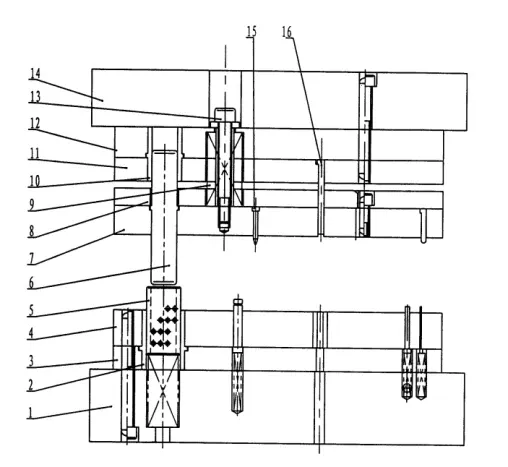
Figure 1 is a schematic diagram of the structure of an existing progressive stamping die.

Figure 2 shows the effect diagram of the parts produced by the existing progressive stamping die. In Figure 2, the lower right image is a schematic diagram in direction A.
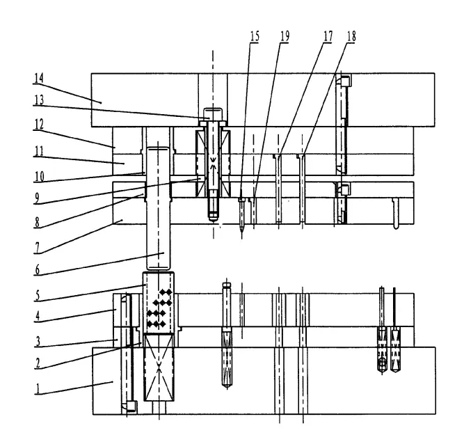
Figure 3 is a schematic diagram of the structure of an embodiment of the present utility model.
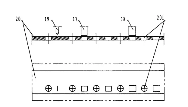
Figure 4 is a schematic diagram of the stamping production process of the embodiment of the present utility model.
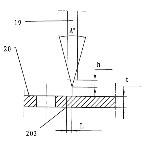
Figure 5 is a schematic diagram of the rib cutting convex mold in the embodiment of the present utility model.
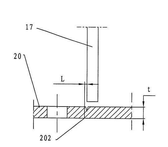
Figure 6 is a schematic diagram of a pre cut convex mold according to an embodiment of the present utility model.
Embodiment
The following embodiments will further illustrate the present utility model with structural drawings.
As shown in Figures 3 and 4, the present utility model has made improvements on the existing progressive stamping die (see Figure 1). The progressive stamping die is equipped with a lower die seat 1, a lower guide sleeve 2, a lower cushion plate 3, a concave template 4, a retaining ring 5, an inner guide column 6, a discharge plate 7, a height limiting plate 8, a discharge spring 9, an upper guide sleeve 10, a fixed plate 11, an upper cushion plate 12, a discharge screw 13, an upper die seat 14, a guide nail 15, and a convex die. The convex die is equipped with a rib cutting convex die 19, a pre cutting convex die 17, and a precision cutting convex die 18. Divide the stamping production process of parts into three steps: rib cutting+pre cutting+precision cutting; At a certain step in the progressive stamping die, a rib cutting convex die 19 is set up, and a rib cutting groove is correspondingly punched out on the strip 20 (with a guide hole 201 on the strip). In this mold, at a corresponding position in a subsequent step, the pre cut convex mold 17 cuts off the rib groove and roughly cuts out the end face of the part. The position is at a certain distance from the part position, and this distance is the precision cutting allowance; At a subsequent step, the precision cutting punch 18 is used to cut off the precision cutting allowance at the corresponding position, and the shape of the part is precisely cut out.
In Figure 5, the cutting angle A of the rib punch 19 can be selected as 20 °~60 °, and the cutting depth h is (0.2~0.5) t, where t is the thickness of the stamping material, usually 0.8~5mm; L is the distance between the position of the part and the center of the cutting rib, ranging from 0.1 to 1mm.
In Figure 6, L represents the distance between the position of the part and the pre cut punch, ranging from 0.1 to 1mm.
2025 March 3rd Week WBM Product Recommendation:
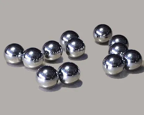
High Chrome Steel Balls:
G5,G10,G16 Our Chrome ball usually produce according to GBT 308.1-2013 and ISO 3290-1:2014 standards. Hardness will be customized base on your requirement.
https://www.bearingroller.com/rolling-elements/steel-ball/high-chrome-steel-balls.html