Abstract
A large driving wheel hammer upper forging die, comprising: upper die, lower die, equipment hammer head, equipment gripper; The upper mold is fastened to the equipment hammer head through wedges and keys, and the lower mold is fastened to the equipment clamp through wedges and keys; The upper mold lock, upper mold compartment, upper mold outer ring bridge, upper mold cavity, upper mold inner ring bridge, upper mold skin storage bin, and upper mold impact surface in the upper mold are directly processed on the upper mold; The lower mold lock, lower mold compartment, lower mold outer ring bridge, lower mold cavity, lower mold inner ring bridge, lower mold skin storage bin, and lower mold bearing surface in the lower mold are also directly processed on the lower mold; The upper and lower molds are guided by locking buckles. This device is easy to operate, with stable processing quality, effectively improving the strength and service life of the driving wheel. Easy to achieve mass production, greatly reducing production costs.
Description
A forging die for a large drive wheel hammer
TECHNICAL FIELD
This utility model belongs to the field of forging molds and relates to a large driving wheel hammer forging mold.
Background technology
Drive wheels, also known as sprockets, are widely used in the construction machinery industry. Large drive wheels weigh 30-100 kilograms and have a diameter of 500-900 millimeters. Their structure is shown in Figure 1. Two driving wheels form a group, and tracked construction machinery relies on the teeth A of the driving wheels and the pin shaft of the chain rail joint to transmit motion and travel. The production conditions of the driving wheel are complex and harsh, and it will bear large and uneven impact loads during operation. And due to the fact that machining is not carried out on other parts except for the inner hole, customers have high requirements for the strength, dimensional accuracy, and shape of the driving wheel: the tolerance of all tooth A profiles is ± 3 millimeters, and there should be no residual burrs or burrs that affect the use after trimming. The shape of the outer contour trimming belt is regular and the width is 25 ± 5 millimeters. In order to ensure smooth operation of the construction machinery, the overall flatness of the driving wheel is not greater than 3 millimeters.
In order to ensure the strength and service life of large drive wheels, we have developed a comprehensive forging process for large drive wheels. Due to the need for one-time forging on ordinary forging hammers, the forging die life is low, the material utilization rate is low, and the required equipment tonnage is large. This not only leads to quality defects such as wrinkles and folds, but also results in significant residual burrs and burrs, which pose great difficulties for subsequent repair processes and result in relatively high production costs. Therefore, it is imperative to develop a large driving wheel hammer upper die forging tool with long service life and safe and reliable operation.
Utility Model Content
The purpose of this utility model is to provide a large driving wheel hammer forging die: forging a large driving wheel as a whole on the hammer, with a simple process and long mold life, effectively improving the strength and reliability of the driving wheel.
In order to achieve the above objectives, the present utility model adopts the following technical solution: a large driving wheel hammer upper forging die, comprising: an upper die, a lower die, an equipment hammer head, and an equipment clamp; The upper mold is fastened to the equipment hammer head through wedges and keys, and the lower mold is fastened to the equipment clamp through wedges and keys; The upper mold lock, upper mold compartment, upper mold outer ring bridge, upper mold cavity, upper mold inner ring bridge, upper mold skin storage bin, and upper mold impact surface in the upper mold are directly processed on the upper mold; The lower mold lock, lower mold compartment, lower mold outer ring bridge, lower mold cavity, lower mold inner ring bridge, lower mold skin storage bin, and lower mold bearing surface in the lower mold are also directly processed on the lower mold; The upper and lower molds are guided by locking buckles.
Due to the adoption of the aforementioned technical solution, this utility model can achieve the following beneficial effects:
1) The large drive wheel is forged as a whole using hammer forging, which has good strength and long service life.
2) Using a circular intermediate billet results in high material utilization, requires less forging force, and has a long mold life.
3) By changing the shape of the upper mold teeth, the residual burrs and deformation of the driving gear teeth are reduced when cutting off burrs, reducing the amount of subsequent polishing and trimming. By optimizing the rounded corners of the bridge, quality defects such as creases and folds are reduced.
4) The traditional casting or segmented forging of large drive wheels has been replaced with hammer forging as a whole, which has a simple forming process, novel mold structure, easy operation, stable quality, and facilitates mass production, greatly reducing production costs.
Attached image description
Figure 1 is a schematic diagram of the structure of a large drive wheel;
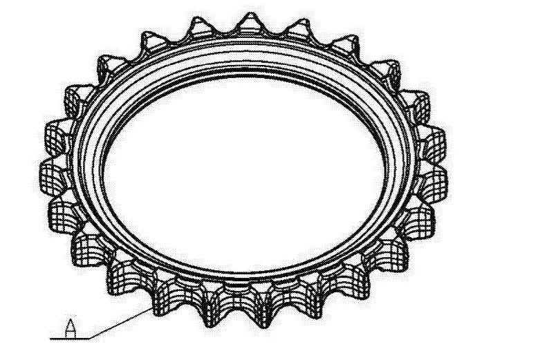
Figure 2 is a schematic diagram of the structure of a circular intermediate billet for large drive wheels;
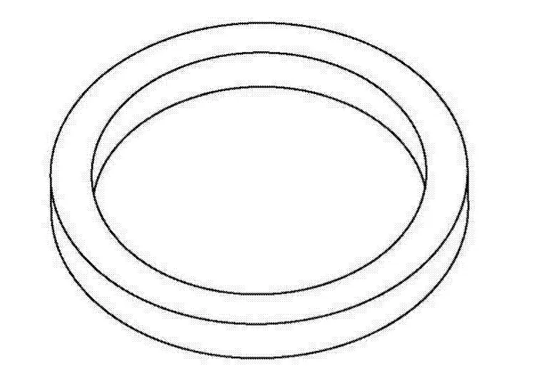
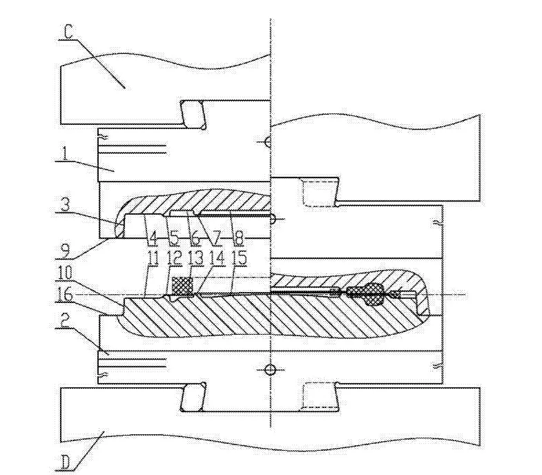
Figure 3 is a schematic diagram of the structure of a forging die on a large driving wheel hammer of the present utility model.
Embodiment
Further description of the present utility model will be made in conjunction with the accompanying drawings, as shown in Figure 3: a large driving wheel hammer upper forging die, comprising an upper die 1 and a lower die 2. The upper mold 1 includes: upper mold lock 3, upper mold compartment 4, upper mold outer ring bridge 5, upper mold cavity 6, upper mold inner ring bridge 7, upper mold skin storage compartment 8, and upper mold impact surface 9; The upper mold 1 is connected to the hammer head C on the equipment through wedges and keys. The upper mold lock 3, upper mold compartment 4, upper mold outer ring bridge 5, upper mold cavity 6, upper mold inner ring bridge 7, upper mold connecting skin storage bin 8, and upper mold bearing surface 9 are directly processed on the upper mold 1.
The lower mold 2 includes: a lower mold lock 10, a lower mold compartment 11, a lower mold outer ring bridge 12, a lower mold cavity 13, a lower mold inner ring bridge 14, a lower mold skin storage bin 15, and a lower mold impact surface 16. The lower mold 2 is connected to the equipment clamp D on the equipment through wedges and keys. The lower mold lock 10, lower mold compartment 11, lower mold outer ring bridge 12, lower mold cavity 13, lower mold inner ring bridge 14, lower mold skin storage bin 15, and lower mold impact surface 16 are directly processed on the lower mold 2; Upper mold 1 and lower mold 2 are guided by locking buckles.
When working: Hammer head C drives upper mold 1 to rise, and places the circular intermediate billet heated to 1150 ℃~1200 ℃ on lower mold 2; Hammer head C drives upper mold 1 to quickly fall. Under the guidance of upper mold lock buckle 3 and lower mold lock buckle 10, upper mold cavity 6 applies kinetic energy to the annular intermediate billet, causing metal to fill upper mold cavity 6 and lower mold cavity 13. Excess outer ring billet flows into upper mold compartment 4 and lower mold compartment 11 through upper mold outer ring bridge 5 and lower mold outer ring bridge 12, and excess inner ring billet flows into upper mold skin storage bin 8 and lower mold skin storage bin 15 through upper mold inner ring bridge 7 and lower mold inner ring bridge 14. Subsequently, hammer head C drives upper mold 1 to rise, completing one strike; After 4-5 consecutive strikes, use a pry bar to lift the billet on the lower mold 2, lubricate and cool the mold with graphite emulsion or other lubricants, place the billet in place, and continue to strike until the upper mold bearing surface 9 and the lower mold bearing surface 16 come into contact, completing forging. The final forging temperature should not be lower than 950 ℃; Use a pry bar to lift the drive wheel, check the thickness, and after passing the inspection, remove it to complete one working stroke.
2025 March 1st Week WBM Product Recommendation:
High Chrome Steel Balls:
G5,G10,G16 Our Chrome ball usually produce according to GBT 308.1-2013 and ISO 3290-1:2014 standards. Hardness will be customized base on your requirement.
https://www.bearingroller.com/rolling-elements/steel-ball/high-chrome-steel-balls.html