
The causes of possible damage of steel ball in the process of ball distribution, ball addition, ball return and ball separation on the automatic assembly machine, improvement measures and precautions.
Abstract: the causes of possible damage of steel ball in the process of ball mixing, ball adding, ball returning and ball dividing on the automatic assembly machine are analyzed, and the improvement measures and precautions are put forward.
Key words: deep groove ball bearing; Assembly machine; Steel ball; damage
Deep groove ball bearing automatic assembly machine (line) has been widely used in bearing manufacturing industry. It is of great significance to stabilize product quality and improve production efficiency. However, during the assembly process, the steel ball is often damaged, mainly in the ball filling, ball returning and ball dividing stations. This is usually due to the improper manufacturing, installation and adjustment of tooling, resulting in the scratch and extrusion injury of the steel ball. The damage of steel ball is very unfavorable to low noise (silent) bearing and must be solved.
1. Match Ball
The ball taking method of automatic assembly machine generally adopts the upper ball box to store the ball. The ball is taken from the up and down reciprocating nozzle installed at the bottom of the ball box. The ball is left in the lower plastic hose and then sent to the aligner, as shown in Figure 1. Generally, there are 10 ball boxes. Assuming that the steel balls of various specifications have equal opportunities to participate in the assembly, there is one tenth chance to send the ball out. The rhythm of the nozzle reciprocating up and down in the ball pile of the ball box is greater than that of the sleeve. For the steel ball with less specified value, the friction time will be longer. In addition, due to the up and down movement of the nozzle, the lower plastic pipe is bent back and forth (Fig. 1b), and the steel ball in the pipe is also squeezed by the small friction of the plastic pipe wall and the steel ball. Especially when there are small particles on the surface and pipe wall of the steel ball, it is easy to cause the scratch and scratch of the ball.
Therefore, the measures taken are: make the ball box into a funnel shape, that is, the bottom is in a slope shape. In order to prevent the funnel mouth from not dropping the ball due to the congestion of the steel ball, install a flat push rod with slight up and down movement at the edge of the funnel mouth to break the congestion of the steel ball (Fig. 1c); And fully keep the steel ball and lower ball pipe clean.
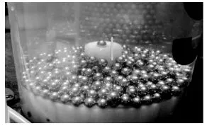
(a) Ball box
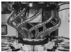
(b) lower ball pipe
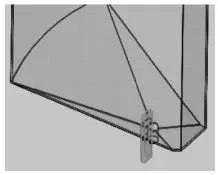
(c) Improved ball box bottom
2. Add Ball
The actual structure of the ball adding part is shown in Figure 2.
2.1 Ball out
The ball outlet enables the steel ball to fall freely and smoothly on the ball bearing crescent platform, and evenly spread to both sides into the channel. The upper part of the ball outlet is provided with a push rod. When the ball is smooth, the push rod starts to move downward after the ball is all on the crescent platform, but does not touch the ball (empty action); When the ball is not smooth, the downward movement of the push rod will push the steel ball that has not yet flowed down and force the ball out. At this time, it is easy to produce crushing injury and surface scratch of the steel ball.
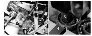
1 - detection device; 2 - push rod; 3 - Crescent platform; 4 - outer ring deformation force adding device; 5 - inner ring positioning device
Fig. 2 physical structure of ball adding part
Therefore, the improvement adopts the ball outlet structure as shown in Fig. 3. The ball outlet is flush with the end face of the bearing, the crescent shaped opening is a circular arc bell mouth, the circular arc radius of the center of the bell mouth is consistent with or slightly smaller than the diameter of the pitch circle of the bearing ball group, and the size radius R in the bell mouth is 1.5 times the ball diameter. The improved ball outlet avoids the overlap of the upper and lower balls, which avoids the occurrence that the lower ball is not smooth and is pushed out by the pressure of the push rod.
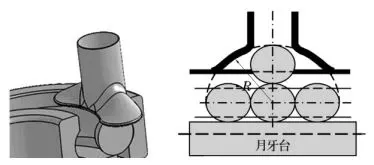
Fig. 3 ball outlet
2.2 Ball drop
At present, the crescent platform used for ball filling can only move up and down. Considering the reset of the inner ring, the width of the crescent platform is limited by the diameter of the retaining edge of the inner and outer ring. When the inner ring leans to one side to give way to the ball filling area, the gap between the inner side of the crescent platform and the retaining edge of the inner ring is large (Fig. 4). The steel ball is easy to fall into this gap and is not conducive to ball separation, which increases the probability of crushing injury between the ball and the retaining edge and may also cause the depression of the middle edge of the inner side of the crescent platform.
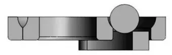
Figure 4 structure of existing platform
In order to make the platform close to the middle of the ball filling gap as much as possible, the existing platform is changed into a split combination structure. The improved platform is shown in Figure 5. The upper crescent can slide back and forth on the lower base, and the inner ring moves towards the outer ring, and the rear crescent rises. The designed upper crescent is just in the middle of the ball filling gap, preventing the ball from falling into the gap between the crescent and the retaining edge. After the ball is filled, the inner ring is reset. At this time, the upper crescent is pushed away with the retaining edge of the inner ring, which does not affect the reset of the inner ring; When the crescent platform drops off the bearing as a whole, the upper crescent returns to the original position of the lower matrix.
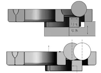
Figure 5 improved structure of crescent platform
3. Return Ball
The ball return plate is used to close the ball to a fixed angle position, so as to facilitate the next step of ball separation and cage installation. The current ball return plate structure is shown in Figure 6, which is inserted into the assembly with the ball from top to bottom. When the side of the ball return plate is in the shape of spiral surface, due to the spiral angle, the steel ball is affected by a spatial force (Fig. 6b) during insertion, and its horizontal component is a circumferential tangential force, which pushes the steel ball to the circumferential direction and returns to both sides. However, at present, the side of the return plate is mostly triangular inclined, and it is more inclined outward after manual repair in use, which increases the pressure on the outer ring channel and increases the probability of damage to the steel ball. In addition, the axial component of the screw facing the steel ball will increase the friction between the steel ball and the channel when it returns to both sides. If the cleanliness of the ferrule and the steel ball is not ideal, it will also cause the scratch between the channel and the steel ball.
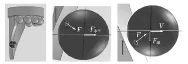
Fig. 6 force analysis of ball and return plate
Therefore, the side of the return ball plate should be made into a spiral surface with standard shape and smooth surface; In order to increase the helix angle as much as possible and reduce the axial component, the ball return plate should be lengthened; The insertion direction of the ball return plate is preferably from bottom to top to offset part of the axial force acting on the steel ball. If the ball return plate is inserted upward from the lower part of the bearing, the steel ball tends to slide down along the spiral surface, which can reduce the axial component force on the steel ball during insertion.
Another ideal way to return the ball is to insert the ball return plate with small top angle (similar to the needle shape of the ball splitter) into the steel ball assembly, and make a circular motion along the pitch circle diameter of the steel ball group to return the ball to one side, which can also eliminate the effect of axial component force.
4. Ball Splitting
The ball splitting fork is used to split the ball (Fig. 7). The key to making the ball splitting fork is that its end should be spiral. The side of the ball splitting fork (especially the side pushing the steel ball) should pass through the axial plane of the center. During ball splitting, the steel ball will be subjected to circumferential tangential force to reduce the friction resistance when the steel ball moves in the channel and avoid scratch; A certain clearance shall be reserved on the other side of the ball splitting fork. Similarly, the ball splitting fork is inserted upward from the lower part of the bearing to reduce the axial component force on the steel ball during insertion and reduce the friction damage to the steel ball.
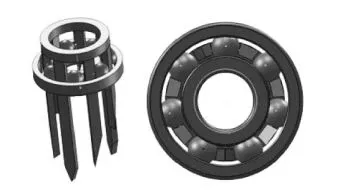
Figure 7 split fork
5. Conclusion
Steel ball is the most critical part of low vibration and low noise bearing. Any micro scar on the working surface will affect the quality of bearing. Therefore, in actual production, in addition to the quality of steel ball itself, we should also pay attention to all details of bearing assembly process. In addition to careful analysis, the solution of these problems also depends on the rationality of tooling manufacturing and adjustment, and needs to be replaced regularly.
More about WBM Steel Ball:
Bearing steel balls are important basic components in the industry. Bearing steel balls have a long history of use in the precision bearing industry and life, and are more widely used. It can be said that steel balls exist in most places where there is rotation, commonly known as steel balls and balls. Steel balls are widely used in bearings, hardware, electronics, iron art, mechanical equipment, electric power, mining, metallurgy and other fields.
WBM now have the ability to supply full set tooling for Modler taper roller grinding line. Their tools are well fitted in customer modler centerless grinder and modler end face grinder. And help customer produce high precision rollers with low cost.
WBM has obtained the certificates of ISO9001:2000 and ISO/IATF16949, The outstanding reputation of WBM is built on our core management principles: technical innovation, high output quality and efficiency, hard-working, meeting and beyond clients’ expectation. WBM spares no effort in creating maximum value for customers.